| Manufacturer: | The Launch Pad  |

(Contributed - by Tim Burger - 05/01/02)
 Brief:
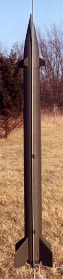
This is a light, nearly 40-inch long, model of a Russian missile. My version
includes an ejection baffle, and makes an allowance for the additional length
of the new Estes E9 motors.
Construction:
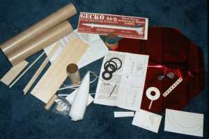
One of the local hobby shops carries The Launch Pad's products. This one went
unsold until it was the last one of a shipment and I thought it needed a good
home. The kit was packaged in a clear plastic bag, and came with a medium grade
of balsa, a pair of thin walled 2.6 inch paper tubes, a 3-inch long motor tube,
and a variety of other parts. The only odd part of this kit is a paper cone
that gets glued to the front of the nose cone to create that military missile
profile. It also sports a boattail.
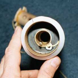
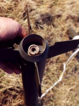
Construction starts with gluing together the motor mount. Since the new Estes E9 and Aerotech F21 motors are longer than the D12 and Aerotech RMS motors I made a change to the way the mount is made. A longer motor tube was substituted for the kit's, and I bent the top hook of the motor hook back 180 degrees, and then hooked that behind the forward centering ring and adjusted the position of the ring such that the other end of the hook hangs off the end of the tube about a quarter inch. Then I glued a motor block into the tube so that it is 90mm from the hook end of the tube. I made sure of the spacing with a spent E9 motor I keep on my workbench for this job. The rear ring was glued on per the instructions, and a paper wrap was glued down to hold the motor hook. (This model is a scale model so it's barely stable as it is. Adding weight aft can cause trouble so this model's balance was very carefully checked before it was flown.)
To create the boattail, the kit provides a 4 1/2 inch long piece of 2-inch diameter tubing, a pair of centering rings to center this in the 2.6-inch tube, and a paper shroud that you cut from a sheet of heavy paper. Shrouds can be tricky so I took my time with this to ensure success. To make this little job a tiny bit easier, I added a 1/8 inch hoop to one of the centering rings (this can be cut from stock 2.6-inch tube, or the coupler). In doing so, it forms a lip for the forward part of the shroud to ride on. The rings were glued onto the outside of the adapter tube as shown in the instructions, but being careful to position the ring with the 1/8-inch hoop aft. When cutting out the shroud, I was careful to leave the lines to allow plenty of material for trimming. By test fitting, trimming a little, and then test fitting again I was able to sneak up on the correct size. The forward part of the shroud was just big enough to match the outside diameter of the airframe tube. The shroud was then glued onto the adapter assembly. The motor assembly was then glued into the adapter with the aft edge of the motor tube positioned an inch and a half from the bottom of the shroud. This seems pretty deep, but it works OK on my HARM missile.
 The kit provides the
familiar triangular paper mount for the shock cord, and a length of 1/4-inch
elastic for the shock cord. I like something that's easier to replace since my
rockets tend to last more than 20 flights. The solution that I've hit upon is
to run a length of 1/8-inch shrink tube through small holes made in the
centering rings. The tube runs the whole length of the motor tube and is used
as a guide for a 200# Kevlar®
line. The Kevlar®
is threaded through the shrink tube and the lower end is tied around the motor
mount. A dab of RC-56 glue holds it there. A loop is then tied in the Kevlar®
a few inches above the motor tube; this loop will be below the top of the
rocket body when it is assembled. One end of the elastic is tied to the loop,
and the free ends of both the Kevlar®
and elastic are tied to the nose cone. The Kevlar®
is long enough to allow the elastic to stretch, but backs it up in case it
fails. The holes need cut, and the shrink tube needs threaded and glued in
prior to gluing the motor assembly into the airframe. The instructions have the
builder attach the nose cone to the rest of the rocket with a 10" long
piece of 'chute shroud line. This is a bad idea, in my opinion - that cone is
pretty heavy with all that ballast and won't last long hanging by a thread like
that.
The kit provides the
familiar triangular paper mount for the shock cord, and a length of 1/4-inch
elastic for the shock cord. I like something that's easier to replace since my
rockets tend to last more than 20 flights. The solution that I've hit upon is
to run a length of 1/8-inch shrink tube through small holes made in the
centering rings. The tube runs the whole length of the motor tube and is used
as a guide for a 200# Kevlar®
line. The Kevlar®
is threaded through the shrink tube and the lower end is tied around the motor
mount. A dab of RC-56 glue holds it there. A loop is then tied in the Kevlar®
a few inches above the motor tube; this loop will be below the top of the
rocket body when it is assembled. One end of the elastic is tied to the loop,
and the free ends of both the Kevlar®
and elastic are tied to the nose cone. The Kevlar®
is long enough to allow the elastic to stretch, but backs it up in case it
fails. The holes need cut, and the shrink tube needs threaded and glued in
prior to gluing the motor assembly into the airframe. The instructions have the
builder attach the nose cone to the rest of the rocket with a 10" long
piece of 'chute shroud line. This is a bad idea, in my opinion - that cone is
pretty heavy with all that ballast and won't last long hanging by a thread like
that.
 The motor mount and shroud
assembly was then glued into one end of the longer airframe tube, and glue
fillets were made at all ring and paper joints. The tube joiner was then glued
half way into this tube. The top airframe tube was then added, taking care to
get the parts together straight by rolling them on a flat surface while the
glue was still wet. When dry, the airframe spirals, airframe joint, and
boattail joint were filled with Elmer's Fill 'n' Finish and sanded smooth. If
everything is done correctly, the joints and spirals should disappear under the
primer coat.
The motor mount and shroud
assembly was then glued into one end of the longer airframe tube, and glue
fillets were made at all ring and paper joints. The tube joiner was then glued
half way into this tube. The top airframe tube was then added, taking care to
get the parts together straight by rolling them on a flat surface while the
glue was still wet. When dry, the airframe spirals, airframe joint, and
boattail joint were filled with Elmer's Fill 'n' Finish and sanded smooth. If
everything is done correctly, the joints and spirals should disappear under the
primer coat.
The kit provides a centering ring that is positioned seven inches from the top of airframe to keep the recovery system forward in the rocket for balance sake. A guy could go broke trying to feed large models like this wadding so I added an additional centering ring and a short section of BT-60 to create an ejection baffle. Note that these parts only add about an ounce of weight, and are forward of the CG.
The patterns for the fins were cut from the printed card stock, and used to draw out the fins on the provided balsa. The balsa is C grain, and reasonably hard. Wouldn't want a rock hard sheet, but on the other hand contest grade soft wouldn't work out too well either. The root edges and grain direction are clearly marked on the patterns, and the only potential problem is with getting the patterns arranged on the sheets in such a way that you have enough material to make all the fins that you need. There was plenty, but not so much to allow for mistakes. I used a straight metal edge and a sharp blade to get good crisp fins. The four aft fins were then stacked together and sanded to a uniform size. The same was done for the forward fins. I have been unable to come up with a good set of scale drawings for this rocket, and the instructions don't include suggestions for the correct fin profile so I simply made a guess. The forward fins were ground to have a diamond shaped cross section. I made a mark across the root and tip edges and using masking tape as a guide, ground the profile into each fin with a sanding block. The aft fin's cross section was ground to pointy at the front and slightly tapered at the back using the same method. While not perfect, they came out more or less uniform with good crisp lines. The body tube was marked using the fin guide in Harry Stine's Handbook of Model Rocketry and a door jam. The aft fins were then glued to the airframe using Titebond II. The forward fins are actually mounted on the nose cone, and that makes getting them on straight just a little tricky. Because it's hard to draw a straight line on a curving cone I used a piece of string to create a guide. The string was taped to the center of the base and stretched over the edge, crossed over the marks (made when the tube was marked) and across the tip of the nose. A line was carefully made along the string being careful not to deflect the string. The fin root edges were sanded to match the cone's curve and were then glued down using thick CA. A few drops of thin CA was put on the tip of all eight fins. The CA wicks through the fins along the grain and serves to make them strong. The instructions indicate that the fins should be painted with thin CA. If you do that be sure to sand them smooth again within a few hours or they will be very hard to sand. Fillets were made at all fin roots using epoxy. I like epoxy for fillets because it makes a glass smooth fillet, but one must use care to not over use it due to it's heavy nature. Also, this is a scale rocket, and the real ones usually have a sharp corners where the roots meet the airframe, this is particularly true for guidance fins.
The scale wiring conduits were cut and sanded to shape and placed on the airframe as shown in the instructions. Sanding these was a little tedious but the sanding block helped. When the glue was dry, I used Elmer's Fill 'n' Finish to fill in any gaps, and created a smooth clean edge with sandpaper.
The provided launch lug was cut into two equal pieces, and glued on a line with one piece at the joint between tubes, and the other a few inches from the bottom. A length of launch rod was used to ensure that they are straight. I added an additional set of 1/4" lugs next to those because I really hate to change rods between rockets. Fillets were added when dry.
The paper nose "hat" was cut from the paper stock, and rolled into a cone. This is a bit tricky to do so that you get a good sharp point. This hat is then glued to the front of the cone. I thought that getting this hat on straight would be difficult, but I was pleasantly surprised to find it wouldn't be a problem. The hat is small enough, and the curve of the cone is fat enough that they come into contact and are self centering. I drew a line around the bottom of the hat while holding it in position. Then I removed it, ran a line of slow CA just above the line, and placed it back on. Voila, no fuss, looks fine. It was painted it with fast CA, per the instructions. It needed it too because the sharp point is fragile. I bent and busted the tip off while messing around with the motor and checking the nose weight. This was fixed with a little dab of JB Weld and sanded back to shape. I used Elmer's Fill 'n' Finish to fill in around the base of the hat to hide the edge of the paper. The nose also needs some weight for balance, unfortunately the supplied clay was dry and rock hard. I used a scale to measure the weight, and substituted some BBs mixed with 30-minute epoxy. I was planning to do this anyway because I've had problems in other rockets with the clay drying out and rattling around in the nose. The center of pressure is shown on the plans at 13" from the base. The balance was checked with the heaviest motor that I had on hand and found to be about 16" from the base - a tad more than a caliber. No further adjustments were made.
The Mylar 'chute was assembled per the instructions. A lot of people dislike these Mylar 'chutes, but I haven't had any trouble with them and they are brilliant in the sky. An 18" 'chute may be a tad small for this rocket - use a bigger one if the ground's hard.
I'd give this kit a rating of 4 out of 5 for construction. Nothing new here, but I wouldn't suggest it for a beginner.
Finishing:
A coat of white sandable primer revealed a few problems with the spiral and in
one place on the boattail joint. These areas were worked on until they are as
smooth and seam free as I could manage. Another thin coat of primer was added
and lightly sanded. The rocket was then painted with three thin layers of
Rustoleum Olive Drab. An easy rocket to finish.
Finishing rating: 5 out of 5 Easy, looks very scale.
 Flying:
The first flight was on March 20, 2002 in my back yard (we have a big yard.)
The weather was cool and clear with very light and variable winds. I had been
launching for an hour or so with zero drift so I worked up my courage and
loaded it on the pad. The motor was an Estes D12-5 and it flew from a
3/16" x 72" rod. Since the motor is recessed pretty far, the rocket
would be scorched from the hot gasses being deflected back from the blast plate
at ignition. To prevent this I used a clothes pin to hold the rocket above the
deflector six or seven inches. This also made connecting the ignitor easier.
The flight was about as perfect as could be, lots of smoke and noise, a good
arrow straight boost, and a nice arc-over with the ejection of the 'chute right
while the rocket was horizontal. Very nice indeed. There was no sign of
scorching or burning in or around the tail cone after the flight. There was a
noticeable accumulation of soot in and around the tail after the second flight,
but still no scorching.
I decided to use a 30" x 18" TLP 'chute rather than the 18" octagonal that the kit came with. Recovery was gentle, and it landed about 10 yards from the pad. No damage despite clipping a tree on the way to the ground.
It was flown again a couple of days later, on another D12-5. More or less the same flight profile, except this time it landed on the shed roof, slid down and hung itself from the tiny tree next to it. Some minor dings on the fins. No worries.
Third flight was at the St. Louis Association of Rocketry's April launch.
The wind was pretty high most of the day, but since the field is so big that
isn't a problem. It was at the end of the day, just after the waiver was
closed. It passed at the check table without comment but the LCO was certain
that it was over the 16 oz weight limit. My reply was "8oz . . . OK, 11oz
with the motor." He questioned that and to avoid any more concern I
 simply handed him the model. He was
convinced! "There's nothing to this rocket!" I picked a long 1/4 rod,
and had to clean the paint out of the lugs before it would slide smoothly. The
motor was an F12-5J and I was a little apprehensive about that since the rocket
isn't officially rated for this motor. Needn't have had any concerns, when the
LCO hit the launch switch the motor lit instantly and the rocket leapt from the
pad. It flew arrow straight on a column of black smoke. Nice arc over, and
ejection just after apogee. Unfortunately, I hadn't spent enough time reefing
the 'chute and it tangled badly - my fault. It landed hard and stripped a fin,
busted a second loose, and and mangled one of the forward fins and actually
took out a plug from the nose! Ouch! Lesson learned: don't rush! The flight was
spectacular though; very scale like with a lot of smoke and noise and very
respectable speed. For me this was the high point of the day even after flying
G64 and F52 motors earlier. This rocket is that much fun.
simply handed him the model. He was
convinced! "There's nothing to this rocket!" I picked a long 1/4 rod,
and had to clean the paint out of the lugs before it would slide smoothly. The
motor was an F12-5J and I was a little apprehensive about that since the rocket
isn't officially rated for this motor. Needn't have had any concerns, when the
LCO hit the launch switch the motor lit instantly and the rocket leapt from the
pad. It flew arrow straight on a column of black smoke. Nice arc over, and
ejection just after apogee. Unfortunately, I hadn't spent enough time reefing
the 'chute and it tangled badly - my fault. It landed hard and stripped a fin,
busted a second loose, and and mangled one of the forward fins and actually
took out a plug from the nose! Ouch! Lesson learned: don't rush! The flight was
spectacular though; very scale like with a lot of smoke and noise and very
respectable speed. For me this was the high point of the day even after flying
G64 and F52 motors earlier. This rocket is that much fun.
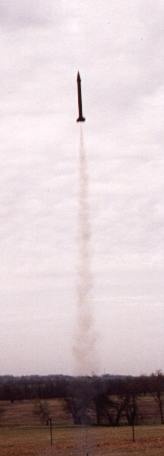
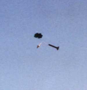
It was repaired the following week and flown again at the April KCAR launch on a D15-4 using a 24" mylar octagonal 'chute. It was a perfect flight; see the photo. It just sort of hung in the sky for a fraction of a second right as the ejection charge fired. It landed about 100 feet from the pads. This was a perfect launch and recovery.
Rating: 5 out of 5 it just doesn't get any better than this.
Cheers & Jeers:
I like the fact that TLP kits come out very light despite my adding baffles and
using epoxy for fin fillets. This is a large rocket and yet it only weighs in
at about 8oz. These kits always perform well in flight and rarely fail to
impress a crowd. Even the high power guys come over to have a closer look after
they've been flown. Good bang for the Buck! The overall quality of the parts is
good. The kit would work fine with the provided shock cord and mount; my
upgrade is solely for longevity's sake. I like that the manufacturer shows the
center of pressure on the plans. This is very helpful when checking the balance
which should be done on any scale rocket, modifications or no.
 I really wish that the
manufacturer would include a parts list. Some scale documentation sources and
fin profiles would also be helpful. The clay nose weight doesn't work out so
well. I would never use a 'chute shroud to attach the nose to a recovery
system, especially when the nose has a lot of ballast in it.
I really wish that the
manufacturer would include a parts list. Some scale documentation sources and
fin profiles would also be helpful. The clay nose weight doesn't work out so
well. I would never use a 'chute shroud to attach the nose to a recovery
system, especially when the nose has a lot of ballast in it.
Specs:
- Length: 39 3/4 inches
- Diameter: 2.6 inch airframe
- 2.15 inch boattail
- Weight: 8 oz
- Recovery: 18 inch, 8 sided, 1/2 mil, Red Mylar 'chute.
- Motors: D12-3, E15-4, E18-4, and F24-7. Also E9-4, D15-4, and F12-5 though these last three are not recommended by the manufacturer and a six foot long launch rod is mandatory with the E9 and F12 (Rocksim says the D15 needs 35 inches). On a calm day I'd use a D12-5 but in 10MPH+ winds a D12-3 would probably be a better choice.
* SPECIAL NOTE off of RMR from Chuck Barndt, President of The Launch Pad
 |
 |
Flights
|
|
|
|
M.A. (February 20, 2009)