| Manufacturer: | Scratch |
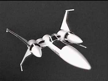
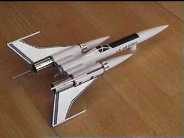
GEMINI STRIKEFIGHTER
by David S. Chen
 FANTASY BACKGROUND
The USAF Gemini Strikefighter was commissioned in 2039, the contract being
awarded to the new Boeing- Douglas-Martin corporation. The Mercury prototype
made its first flight in 2044. The first production example was delivered in
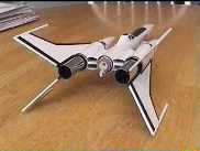
2046 and is represented by this model. The Strikefighter, designated as the
F-48 Gemini was a single seat hypersonic air/space superiority fighter.
Although not able to operate in true space as can the current Apollo
Strikefighter, it was the first fighter capable of operating at the edge of
eart h's atmosphere. Powered by two GE-Rolls Royce scramjet engines, the F-48
operated from both terrestrial bases as well as being air launched and
recovered from the C-211 carrier aircraft. Early examples were equipped with
lower wings that folded into a horizontal position to allow terrestrial
operations. Later examples lacked this feature and operated exclusively with
C-211 carrier aircraft. These versions relied on an emergency parachute
tail-first recovery system should rendevous with a C-211 fail.
 CONSTRUCTION
In the spirit of a true kitbash design, all of the materials necessary to build
this rocket are found in the Estes Gemini DC kit with addition of a 12"
length of 1/8" wooden dowel (I could not find 1/16" dm wooden dowel).
The canopy was cut out of cardstock utilizing a pattern taken from the
"Designers Resource Pack" published by Apogee Components Inc.
(www.apogeerockets.com). Any resemblance of this design to the OOP Estes
Strikefighter is purely intentional. I love the Estes Strikefighter design.
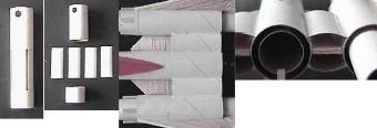
 ENGINE NACELLE
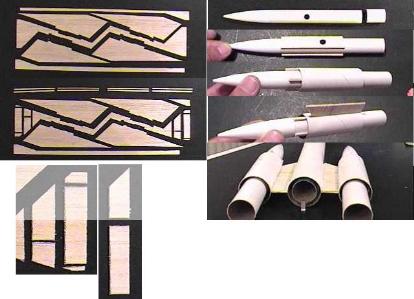
CONSTRUCTION : Cut the balsa fin stock as shown in the photograph such as
to create eight 3" long strips of balsa approximately 3/32" square in
cross section. As illustrated, cut the leftover finstock into two pieces which
are glued together to create one of the two engine struts. The finished struts
are 0.5" wide with a tip chord length of 2 5/8" and a root chord
length of 3 1/8". As shown in the picture, cut the BT-50 tube into an
8" section and two 2 7/8" sections. Save the remaining portion of the
tube (with holes and fin slots) for later. Cut exactly 1" off each of the
two BT-20 tubes. Start by gluing the nosecone into the BT-20 tube (orient the
tube so that the hole is towards the nosecone/tube junction (NTJ). Next, glue
four of the balsa strips around the shortened BT-20 tube starting at the NTJ.
Glue one of the 2 7/8" BT-50 sections over the BT-20/strut assembly,
position it so that it lies 0.5" back from the NTJ. Glue the engine strut
previously assembled to one side of the nacelle paralleling and adjacent to one
of the four balsa strips. Make sure the trailing edge is flush with the rear of
the BT-50 tube. Set aside and allow the assembly to dry thoroughly.
ENGINE NACELLE
CONSTRUCTION : Cut the balsa fin stock as shown in the photograph such as
to create eight 3" long strips of balsa approximately 3/32" square in
cross section. As illustrated, cut the leftover finstock into two pieces which
are glued together to create one of the two engine struts. The finished struts
are 0.5" wide with a tip chord length of 2 5/8" and a root chord
length of 3 1/8". As shown in the picture, cut the BT-50 tube into an
8" section and two 2 7/8" sections. Save the remaining portion of the
tube (with holes and fin slots) for later. Cut exactly 1" off each of the
two BT-20 tubes. Start by gluing the nosecone into the BT-20 tube (orient the
tube so that the hole is towards the nosecone/tube junction (NTJ). Next, glue
four of the balsa strips around the shortened BT-20 tube starting at the NTJ.
Glue one of the 2 7/8" BT-50 sections over the BT-20/strut assembly,
position it so that it lies 0.5" back from the NTJ. Glue the engine strut
previously assembled to one side of the nacelle paralleling and adjacent to one
of the four balsa strips. Make sure the trailing edge is flush with the rear of
the BT-50 tube. Set aside and allow the assembly to dry thoroughly.
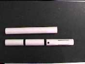 BODY CONSTRUCTION:
Assemble the engine mount as instructed by Estes and glue into one end of the
8" BT-50 tube. Glue the engine tube even with the end of the BT-50 tube.
At the other end, tie together the two shock cords and attach using the Estes
paper fold method. Assemble the BT-50 nosecone. Attach either one of the
12" chutes or substitute with one 18" chute.
BODY CONSTRUCTION:
Assemble the engine mount as instructed by Estes and glue into one end of the
8" BT-50 tube. Glue the engine tube even with the end of the BT-50 tube.
At the other end, tie together the two shock cords and attach using the Estes
paper fold method. Assemble the BT-50 nosecone. Attach either one of the
12" chutes or substitute with one 18" chute.
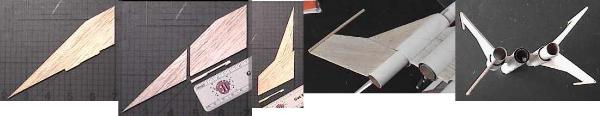
WING CONSTRUCTION: This is the trickiest part. Remove the "fin
slot" portion of balsa from each of the four fins with a sharp razor
knife. Then, utilizing graph paper or a measuring mat, cut the fin in half
using a line that begins at a point that is 2 7/8" from the pointy front
end of the fin (as measured along the root chord) and make sure this line is
exactly PARALLEL to the trailing edge of the original fin. Sand the cut
edge flat and then glue the two sections back together again as illustrated in
the photograph. Make sure the posterior fin half is offset by at least
1/8" or more as illustrated to accomodate the transiton between the BT-50
and BT-20 tubing of the engine nacelles (alternately, the posterior half of the
wing can be glued first to the BT-20 portion of the completed engine nacelle
followed by the anterior half of the wing to the BT-50 portion later). When
dry, cut the 12" 1/8" dm wooden dowel into four 3" sections an d
glue one section to the tip chord of each of the four wings.
 FINAL ASSEMBLY: Glue
each of the two engine nacelles to the body by lining up the trailing edge of
the engine strut with the back end (engine end) of the 8" BT-50 tube. Make
sure the engine struts are parallel to each other and to the ground and that
the engine hook is facing the ground. The double glue technique works well here
as does setting the whole assembly on a flat surface and leaving it undisturbed
until dry. Reinforce the strut to the body with several layers of glue fillets.
As illustrated, take the remaining portion of BT-50 tube (with holes and fin
slots in it) and make two cuts in it at each end of the fin slots to produce
four quarter sections of body tube. Glue each of these body tube sections to
the top and bottom of the engine strut straddling the two BT-50 sections.
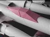
Reinforce with glue fillets. Glue two of the wing assemblies to each engine
nacelle at 90 degrees to each other and along the outside half of the nacelle.
Each fin root should transect the distance between two of the balsa strips.
Some careful sanding of the p osterior half of the root chord may be necessary
to produce a flush fit with the engine nacelle (This step can be omitted by
gluing the back and forward halves of the wing separately to the completed
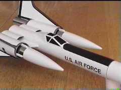
engine nacelle). Reinforce with glue fillets. Construct the canopy and glue it
to the top of the body tube. I placed my canopy such that the back end of the
canopy was 1 7/8" from the back end of the body. Cut the launch lug into
two pieces and glue them along the bottom of the body 2.25" apart from
each other. I offset mine away from the midline so that the launch rod would
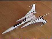
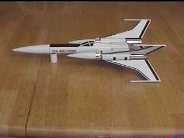
clear the engine hook. I finished my model with two coats of gray primer
followed by two coats of gloss white ("America's Finest" brand sold
by Home Depot) paint. Extensive use of adhesive auto detailing stripe and tape
was used to finish the model. A roll of ordinary vinyl electricians tape was
utilized to create the non-glare black surfce in front of the canopy. The final
weight (without engine) is 2.55 ounces with an 18 inch chute installed. The CG
with a C6-3 Estes engine loaded is exactly at the forward end of the BT-50
section of the engine nacelles.
FINAL ASSEMBLY: Glue
each of the two engine nacelles to the body by lining up the trailing edge of
the engine strut with the back end (engine end) of the 8" BT-50 tube. Make
sure the engine struts are parallel to each other and to the ground and that
the engine hook is facing the ground. The double glue technique works well here
as does setting the whole assembly on a flat surface and leaving it undisturbed
until dry. Reinforce the strut to the body with several layers of glue fillets.
As illustrated, take the remaining portion of BT-50 tube (with holes and fin
slots in it) and make two cuts in it at each end of the fin slots to produce
four quarter sections of body tube. Glue each of these body tube sections to
the top and bottom of the engine strut straddling the two BT-50 sections.
Reinforce with glue fillets. Glue two of the wing assemblies to each engine
nacelle at 90 degrees to each other and along the outside half of the nacelle.
Each fin root should transect the distance between two of the balsa strips.
Some careful sanding of the p osterior half of the root chord may be necessary
to produce a flush fit with the engine nacelle (This step can be omitted by
gluing the back and forward halves of the wing separately to the completed
engine nacelle). Reinforce with glue fillets. Construct the canopy and glue it
to the top of the body tube. I placed my canopy such that the back end of the
canopy was 1 7/8" from the back end of the body. Cut the launch lug into
two pieces and glue them along the bottom of the body 2.25" apart from
each other. I offset mine away from the midline so that the launch rod would
clear the engine hook. I finished my model with two coats of gray primer
followed by two coats of gloss white ("America's Finest" brand sold
by Home Depot) paint. Extensive use of adhesive auto detailing stripe and tape
was used to finish the model. A roll of ordinary vinyl electricians tape was
utilized to create the non-glare black surfce in front of the canopy. The final
weight (without engine) is 2.55 ounces with an 18 inch chute installed. The CG
with a C6-3 Estes engine loaded is exactly at the forward end of the BT-50
section of the engine nacelles.
 FLIGHT REPORT
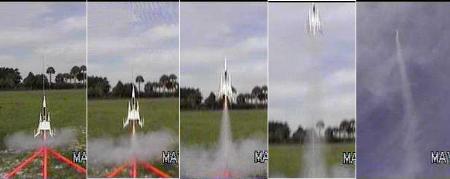
I flew the strikefighter early in the morning with winds less than 5 mph.
The first flight was on an Estes B6-2 engine with a 18" chute. No
problems, flew straight up to around 300 ft and drifted down very slowly.
The second flight was on an Estes C6-3 with a 12" chute. A very
straight flight to at least 600 ft. Unfortunately, it came down on the
roadway surrounding the field breaking one wing. The design is
definitely flight stable for engines weighing as much as an Estes C6-3.
 |
 |