Scratch 38mm Deuce's Wild Original Design / Scratch Built
Scratch - 38mm Deuce's Wild {Scratch}
Contributed by Giacomo Bosso
| Manufacturer: | Scratch |
Introduction
Since first
FlisKits'
Deuce's Wilds have been reviewed on EMRR I've been willing to get one of
them but as soon as
Carl
upscaled 'em it suddenly became a necessity for me to build a similar HPR
clustered model that would to be flown on Aerotech reloads in the 38 mm range.
The first inspiration suddenly turned out to be a stronger desire and that forced me to order some LOC/Precision components that I got by the end of June. I was planning a trip to a Spanish launch during the first weeks of August so construction started.
Relying on LOC components didn't allow me to faithfully reproduce the Deuce's Wild unique nosecone (I didn't have the time to get one turned); apart from that and other minor discrepancies regarding construction techniques and personal building experience/preferences I think I still captured the spirit of such an innovative model.
Construction
Motor mount tubes…
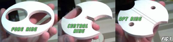
I decided on two (2) motor mount tubes 10-inches long to allow the use of
38/480 hardware; the tubes were angled 10Ž° from the rocket
centerline and that produced the hole pattern for the three (3) centering rings
I custom-made out of ¼-inch birch plywood (FIG.1).
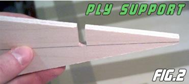
A ¼-inch birch ply triangle was also cut to provide additional support to the mounts (Fig. 2).
 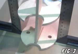     |
The aft and central rings had some holes drilled for further 2-part-foam expansion in the finished fin can. The motor mount tubes' support holes in the CRs were also angled to provide the necessary bonding surface. The subassembly went together pretty easily: the triangle support was epoxied to the aft ring and the central ring was then epoxy-notched making sure everything was square (FIG.3).
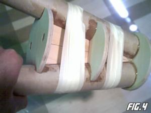
The tubes were next slid into position and the fore ring was added, all parts are epoxied together (the tubes were previously scuffed with very coarse sandpaper to provide the best bonding with the CRs) (FIG.4).
Fins and fin canister…
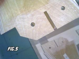
I cut the fins out of 4mm birch ply and laminated them with a single layer of 6
oz/sq.yd fiberglass cloth. Then the fin tabs were notched to engage the central
ring and were drilled to allow foam expansion later on (FIG. 5).
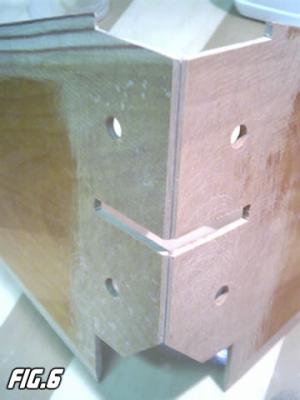
The tab root edges were beveled and the fins were tack-epoxied (5-minute) together to form a pair of sub-assemblies (FIG.6).
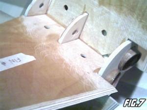
That sub-assembled pair of fins was then epoxied to the motor mount: the central ring was engaged into the tab notches and the tabs themselves were sandwiched between the fore and aft CRs providing adequate anchoring for such large flying surfaces (FIG.7).
Few fillets were made with 30-minute epoxy thickened with chopped fiberglass (structural filling): since two-part-foam was going to be used I didn't want to add useless weight to an already heavy subassembly (around 26.5 oz).
Booster section…
I removed the glassine layer from the LOC tube and filled the spiral groove
with carpenter filler; after it had dried it was sanded smooth with 400-grit
sandpaper.
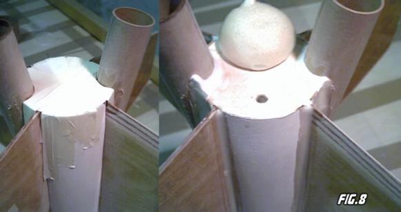
The aft end of the tube was then prepared to accept the fincan: fin slots were cut as well as motor mount tubes “slots;” the whole assembled fincan was then slid inside the tube and epoxied (30-minute). An additional 1-inch long retaining ring cut from a LOC TC-3.90 was simultaneously epoxied in front of the fore CR and seated well against it. Masking tape was used to tighten the whole assembly while it was left curing all night long (FIG.8).
Fin and motor tubes fillets were then made with epoxy and micro-balloons (cosmetic filling); they were sanded smooth with 400-grit sandpaper; two-part-foam was then poured into the fin can through the aft and central rings holes; about two batches were required with cooling periods between them.
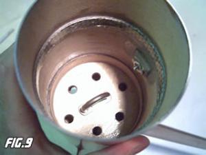 |
The booster was completed as soon as an internal baffled bulkplate (¼-inch birch ply) with a U-bolt was installed (and again retained with a ¼-inch length of TC-3.90 in front of it) as well as a 1 x 1x ¼-inch backing plate with a T-nut was epoxied to provide a solid rail guide mounting support (same solution for the aft rail mounting location just ahead of the aft ring) (FIG.9).
Finally a length (½-inch) of Carbon-Kevlar® reinforced TC-3.90 was epoxied 2.5-inch from the upper edge: it will retain the aft bulkhead of the electronics bay.
Deployment options:
- Single apogee deployment (with or without redundancy) without motor backup:
The rocket falls in one piece and both the aft and fore retaining rings are engaged by the e-bay bulkheads plate; the aft one is plugged (no motor ejection meaning plugged closures or no BP in the forward closures with delay elements correctly installed) while the fore one holds at least one BP can (two (2) if redundant);
- Dual deployment from a single compartment:
As above but the fore bulkhead holds one (1) BP can and a ARRD or similar device; - Standard dual deployment with or without motor backup:
The aft e-bay bulkhead is inside the coupler and holds the drogue-event BP canister;
The aft carbon-Kevlar® reinforced ring works as a sealer and reinforces the booster tube near the edge (almost an anti-zipper); the fore retaining ring is still used to keep the main airframe and the e-bay together and holds the U-bolt and the main-event BP canister;
- Single apogee deployment with motor ejection:
As above but employing plugged bulkheads (no BP canisters required), the main airframe is empty and the main 'chute is contained in the booster section (where the drogue was).
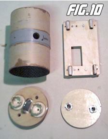  |
Electronics bay…
It is made of a carbon-Kevlar®
reinforced TC-3.90 of standard length (6-inch); a 1-inch long section of
BT-3.90 is epoxied to provide an “outside surface” for both static
ports and electronics external power-up switch (a key-switch in my case)
(FIG.10).
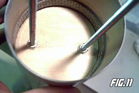
The aft bulkplate (¼-inch birch ply) was drilled for two T-nuts that had to hold the ¼ x 10-inch threaded rods used to support the electronics bed. If employing the single-event deployment described earlier the bulkplate is forced past the carbon-Kevlar® retaining ring, it is flipped and seated against it while the threaded rods are being screwed into their nuts (FIG.11).
If using standard dual-deployment the aft bulkhead must sit against the retaining ring from above meaning that it has to fit inside the TC-3.90 instead of inside the BT-3.90 (in other words you'll need another different bulkplate whose OD equals the TC ID).
The fore bulkplate is made of two (2) ¼-inch birch ply plates laminated together and then drilled for the threaded rods, for the U-bolt and the black powder canister(s); since I was firing redundant apogee pyro outputs I epoxied two (2) PML canister holders from their CPR 3000 system (FIG.10).
The electronics bed was made of 4mm birch ply with ¼-inch LOC launch lugs (about 1-inch long) (FIG.10).
Main airframe…
It was prepared the same way the booster had been: glassine removal and spiral
fillling with final sanding (400-grit); same retention method for the fore
e-bay bulkplate consisting of the ½-inch long carbon-Kevlar®
reinforced TC-3.90 epoxied 2.5-inch from the aft edge.
Finishing
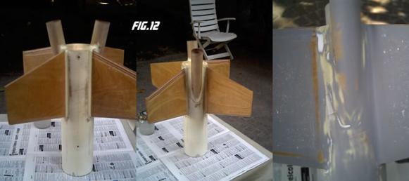
After all the fillets were sanded and everything was smoothed out a first coat
of sanding sealer was sprayed all over the glassine-free model: the tennis-ball
feel of the cardboard became a distant memory after the first 400-grit
sanding…a few more coats of sealer with relative sandings and it was ready
for priming. I used a nitro-thinned car primer that I sprayed three times with
sanding (600-grit) and filling between each coat (FIG.12).
I knew I wouldn't have the time to finish the model with a paint scheme so I left it just primed for its first flight…
Flight preparation
The date (9/10 August) came and we moved out 1200 km to reach our Spanish
friends in Lleida (Cataluna): it was the Third Italian-Spanish Meeting
José Luis Cortijos organized in such a great rocket-launching site, the
Alfés Aerodrome.
On Sunday morning I began prepping the model for the first time while my
friend and Master-rocketeer Stefano Fìgoni assembled the two (2) I218
Redline motors (thanks again!). We opted for these two motors for the following
reasons (in descending order of importance):
- They represented the best compromise in terms of thrust and acceleration and ignition reliability (most of all) between Blue Thunder and White Lightning propellant;
- Their impulse is about 320 Ns (38/360 hardware) meaning a total combined impulse of 640 Ns (which is the upper L1 limit);
- Because of the lack of available reloads they were the only matching engines other than the H123W (too low average thrust).
I tested the new 9V battery (that provided more than 3.7 Amps), mounted the PML Co-pilot (RRC2) on its bed and slid the bed onto the previously installed threaded rods; the key switch was connected as well as the Daveyfire e-matches: a continuity test took place and then the canisters were filled with about 1 gram of BP each. The main airframe was secured, tightening the fore bulkplate nuts and the Rocketman R7C in its medium deployment bag was pushed inside the 4-inch tube; a 24” nylon 'chute was used as a pilot to ensure R7C extraction and 15' of ½-inch of tubular nylon was used as a shock cord. I filled the LOC PNC-3.90 with about 10.5-oz of weight to achieve more than two calibers of static margin between the CG and the CP (with the motors I planned to use). The engines were finally loaded, friction fitted and secured with both masking tape and a single machined screw; they were not going to fire the ejection charges so we figured out that this retention method could be enough (I didn't get the Aeropack retainers I'll be using for the next flights). It was weighted and sported out 8.8 lbs!!!
I had prepared some Magnelites ML-24 with one fold, we tested them and chose the ones with matching resistance values (about 1.2 Ohms).
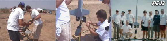
The rocket was loaded onto the rail (almost 100-inch long), the rail itself was strongly secured to the ground, igniters were loaded and the altimeter was armed…(FIG.13)
Flight and Recovery…
 Our LCO Cristiano Casonati (who had helped
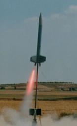
me a lot before the flight) pushed the button and… both motors chaffed!!
Some milliseconds (that seemed minutes to me) passed and the left engine
ignited abruptly lifting the rocket off the pad… everything happened so
fast that I didn't have the time to realize that my worst fear was coming true
under my own eyes: a single motor ignition!!! (FIG.14)
Our LCO Cristiano Casonati (who had helped
me a lot before the flight) pushed the button and… both motors chaffed!!
Some milliseconds (that seemed minutes to me) passed and the left engine
ignited abruptly lifting the rocket off the pad… everything happened so
fast that I didn't have the time to realize that my worst fear was coming true
under my own eyes: a single motor ignition!!! (FIG.14)
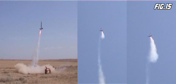
The rocket left the pad on one motor, slightly drifting as it cleared the rail but boosting straight and true; then the first I218R died (1.53 sec of thrust) and the right one came to pressure to boost the inherently stable rocket to 2286 ft!!!! (FIG.15)
The Co-Pilot separated the nosecone past apogee (I'll enlarge the static ports a bit), the Rocketman bag was ejected and the pilot extracted the R7C to slow down descend ‘till touchdown about ¼ mile from the pad (I'm sorry I do not have any recovery-related picture… you'll have to trust me!).
Post-recovery inspection…
It is a very important and delicate phase in a rocket flight and shouldn't be
underestimated. Both casings had been retained and both charges had been fired;
everything looked fine apart from a fin scratch caused by a stone during
touchdown.
Lessons learned…
- Upscaling is not a simple matter of enlarging geometric dimensions by a choosen numerical scale factor: both the construction and flying complexity do not follow the same linear law!!!
- Adding too much pyrogen (my fault) to the igniter wire leads doesn't ensure a better ignition; it seems like the big volume of gases produced by the burning mixture inhibits somehow the propellant initial combustion;
- The model can fly on one motor whose average thrust is equal or greater than that of a I218R multiplied by cos(10Ž°)=0.98; I would reccomend H242Ts (240) and I211Ws (480);
- Deuce's Wild!!!!!!
Conclusion
This first flight was half of a failure: we missed the two red flames and the
two separate smoke trails whose scenographic effect is the key of the model's
success (and Carl did a great job in upscaling many times that effect!!!!). On
the other hand it proved that my design worked just fine giving us the
opportunity to experiment some more flights without worrying about potential
catastrophes related to asymmetric thrust (no one would have bet a cent on a
“safe and successful” one motor flight…).
I'll now finish the model with a good-looking paint scheme (that will match the colors of the R7C), correct some aspects and launch it again as soon as possible (maybe not even this year unfortunately).
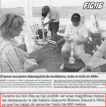
I enjoyed this project very much and would like to thank Jim Flis for having had that superb idea (I'll be waiting for the 3 motors model!), Carl Tulanko for the inspiration, my friends Stefano and Cristiano for all the support they provided and the Spanish team (José Luis Cortijos and Cinto Vìllar for the great lift-off pictures he is able to capture) that made it possible (check out the local news the day after!!!) (FIG.16).
Feel free to contact me at g_boxwood@yahoo.it for any comment and suggestion/advise.
 |
 |