Scratch UPS Express Original Design / Scratch Built
Scratch - UPS Express {Scratch}
Contributed by David Kneble
| Manufacturer: | Scratch |
 Brief:
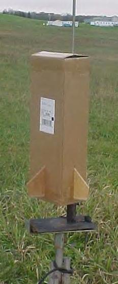
This is a single stage high power rocket created from a UPS shipping box. It flies on 38mm motors (I211W-J350W) and features parachute deployment.
Construction:
The parts for this rocket are all pretty simple and in my case I had everything, but some hardware and the mailing tubes, lying around the house.
After the destruction of a section of one of my other rockets, I ordered the necessary replacement parts. They arrived in a 9x6x33 cardboard box. After repairing the other model, I thought of turning the box that the parts came in, into a rocket. So, first I worked out the rocksim file which I will discuss a little later. Then I began to buy and cut the parts I needed. They were as follows: 1 box, 1 38mm MMT, 4 3/16" ply fins with the necessary fin tabs (on one side of the box the tabs are longer), two 3/16" ply centering rings for 9x6 to 38mm, one 3/16" ply centering ring for 9x6 to 3," one 3" mailing tube, 15' of 9/16" tubular nylon, 2 2" long pieces of 1/2" LL material, u-bolt, motor retention hardware, nuts, bolts and lead fishing weights and adhesive (epoxy and liquid nails).
To begin construction, after the rings and fins had been cut out, I epoxied the 38mm tube to one of the centering rings. This would be the forward end of the MMT. Then, I determined how far in the MMT should slide so that 1/2" protruded from the flaps of the box, at the aft end, if the flaps were sealed. The second 38mm centering ring was slid onto the aft section of the MMT but not epoxied. The MMT and CR's were placed in the box at their respective locations and a bead of liquid nails was applied to the joint between the forward edge of the forward CR and the box. After the adhesive set, fin slots were cut into the box at the correct locations. The fins were tacked to the motor mount with epoxy and then filleted with more epoxy internally, but not externally to maintain the rough look of the box.
The aft centering ring had the t-nuts for motor retention installed and then it was glued in place with liquid nails. The flaps at the rear of the box were trimmed to allow the MMT to protrude through and then they were folded over and sealed tight with packaging tape.
Then, the 3" mailing tube was cut to the length, that was internally between the forward centering ring and the forward edge of the box. I believe this was about 28" or so.
Then, on the final centering ring (9x6x33 to 3") a u-bolt was installed and then two bolts were installed through the ring (at opposite ends or the CR) so that they protruded about 2" above the front side of the ring (the same side with the u-bolt protruding). This centering ring was glued onto the mailing tube about 3" from one end using liquid nails to seal any gaps.
Then, the mailing tube and CR assembly was epoxied into the box with the CR closer to the front of the rocket so that the bolts were visible. The ring joint was filleted and allowed to dry and the tubular nylon was attached to the u-bolt.
Fiberglass was applied to the forward flaps so that they were strengthened but still able to fold shut and form a "nose" for the rocket.
Finally, two 1/2" LL's were epoxied onto one side of the box along one of the fin joints.
 Flight:
My next chore was to determine how much nose weight was necessary to make the box stable. For this I turned to rocksim. Because rocksim can not create boxes for airframes I had to compromise. Because my primary goal was to find the center of pressure so that I could move the CG forward of it, and because CP is greatly influenced by drag of all different types, my goal in rocksim was to create a rocket airframe with similar amounts of drag to the box.
Drag of an airframe is based on a lot of things, but because I lack a degree in the field of fluid dynamics I was withheld to using only the shape and surface area determiners of drag.
Using some simple equations I found the frontal surface area of the box and then created a circle with the same area, which became the basis for the diameter of the tube. Following, I found the area of the sides of the box and then created an airframe of equal area, which became the primary information in determining the length of the tube.
Then, I created the NC, which was simply the flaps on the box. I found when closing the box that they were not completely flat but had a slight arc like a NC has. So, my NC in rocksim has a diameter equal to the body diameter but only .1" long, relatively flat.
The rest of the rocksim file is pretty self- explanatory.
Using this file, I found where the CG needed to be in order to be in front of the CP calculations for both methods. Then I added nose weight until the CG met the requirements and then weighed the model for accurate reference.
After running rocksim for flights of varying motors I found that motors from an I211 and up yielded satisfactory altitudes and velocities.
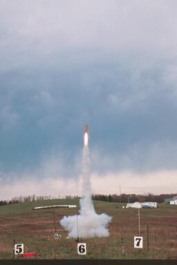
I went to the monthly NEPRA launch and the weather seemed okay, not too windy, so I considered my motor options. After talking to a fellow rocketeer, he informed me that there are very many serious equations that need to be done when testing something like this, to determine how much stress the object will undergo, because of its frontal shape; a square. Slightly nervous, I opted for the I211, a nice easy motor for this rocket, with hopefully not too much stress.
My dad and I prepped the rocket, loading the motor and attaching the 54" chute, and then taping the flaps closed with a small piece of masking tape.
The rocket was loaded onto the pad, which had a 10' 1/2" launch rod to keep the rocket as stable as long as possible.
After a couple of tries at lighting it, it finally came to life and rose, quite quickly, into the sky above. The flight was great with no real signs of instability and the rocket arched over. The charge fired at 6 seconds but the chute failed to deploy; it got caught up in the fiberglassed flaps. The rocket hurtled toward the earth and in an epic battle, the ground gave the box rocket a fatal blow. There wasn't much left but in my mind the flight was successful because it was stable.
I suspect that the chute failed to deploy because the air resistance on the flaps forced them closed too quickly and didn't allow the chute to fully escape the mailing tube.
I am working on an upscale version of this rocket, 10x10x48, which will feature dual rear ejection deployment to avoid the air resistance problem. The planned flight for this box is next spring, possibly at NSL 2003, on a J415W.
Summary:
The pros of this rocket are it's simple design and construction, impression on the RSO when he sees it, and its low, majestic flights.
The cons of THIS box rocket are the limited number of possible motors and poor recovery design.
 |
 |