Scratch Leif Erickson Original Design / Scratch Built
Scratch - Leif Erickson {Scratch}
Contributed by John Thompson
| Manufacturer: | Scratch |
Brief:
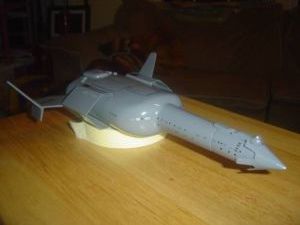
My entry for the EMRR 2008 Design this Spaceship contest. I would rate this as a skill level three model. It is not a
complicated build, but the modeler must use CA and epoxy to adhere different materials to each other. The modeler must
form shrouds from cardstock, and this build requires using a power drill which a beginning modeler might not have the
skills to use.
Construction:
Parts list:
| Name | Quantity | Length | Part Number |
|---|---|---|---|
| Engine Tube | 1 | 2.75 inches | BT-20J |
| Body Tube | 1 | 9.75 inches | BT-50H |
| Fuselage | 1 | 6.5 x 4 inches | Plastic Bottle |
| Nose cone | 1 | 2.75 inches | PNC-20A |
| Launch Lug | 1 | 2 3/8 inches | LL-2AM |
| Shroud Sheet | 1 | 8.5 x 11 inches | PS-001 |
| Decal Sheet | 1 | 8.5 x 11 inches | DS-001 |
| Balsa Sheet | 1 | 4 x 6 inches | BS-001 |
| Kevlar® Cord | 1 | 10.75 inches | KV-001 |
| Parachute | 1 | 12 inch | PK-12A |
| Centering Rings | 2 | CR-2050 | CR-2050 |
Construction begins with the usual engine tube assembly. Using a pencil, make a mark on the 2.75 inch BT-20 body tube ½ inches from one end. Make a second mark ½ inches from the other end. Glue the thrust ring into one end of the engine tube, making sure the thrust ring is flush with the end of the tube.
Next, run a bead of glue around the outside of the engine tube behind one of the marks you made in the earlier step. Take one of the CR 20/50 centering rings and slide it onto the engine tube from the opposite end of the glue bead. Slide the centering ring through the glue up to the pencil mark. Take the other centering ring and slide it onto the engine tube past the second mark. Run a bead of glue around the engine tube behind the second pencil mark and slide the second centering ring through the glue up to the second pencil mark. Apply fillets to both centering rings.
Wrap the Kevlar® thread around the engine tube, behind the centering ring, that is on the same end as the thrust ring. Spread some thin CA over the Kevlar® wrap to give it a strong bond to the engine tube. Next, using your hobby knife, cut a groove in the top of the centering ring. The Kevlar® thread will rest in this groove and will make it easier to glue the engine mount assembly into the main body tube. Set the assembly aside and allow it to dry.
Glue the engine mount assembly into the main BT-50 body tube by placing wood glue on a small dowel and spreading it around the inside about 2.5 inches from one end of the BT-50 tube. Run the exposed Kevlar® thread through the thrust ring of the engine mount assembly, and out the other end. You do this so the Kevlar® thread won't interfere with installing the engine mount. Slide the engine mount partly into the main body tube. Run wood glue around the exposed centering ring then slide the mount the rest of the way into the tube. The aft end of the mount should be flush with the aft end of the body tube.
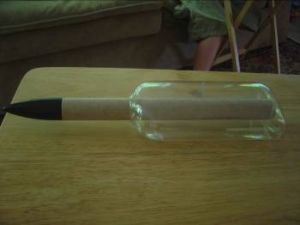
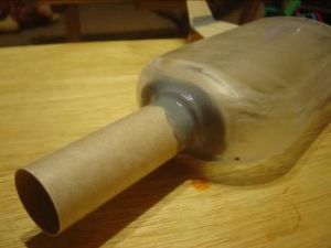
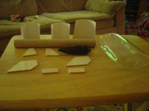
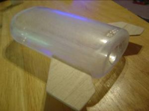
Use a sharp knife or a saw to cut off the threaded portion of the plastic bottle. Take your drill and drill a pilot hole in the bottom of the bottle as close to the center as possible. Widen the hole in the bottom using bigger bits (or a spade bit) until the BT-50 body tube can slide easily through the hole. Remove all paper labels and adhesive from the outside of the bottle. Finally, take some heavy grit sandpaper, 150 or 180 grit, and sand every inch of the outside of the bottle. The sandpaper marks will allow better epoxy and primer adhesion to the plastic.
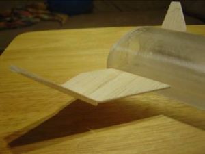
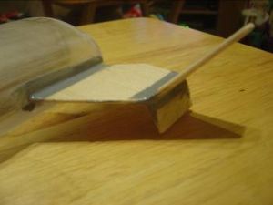
Use the supplied template and cut out the two main fins, the two upper, and the two lower winglets. Round all edges except the root edge with sandpaper. Take one of the large main fins and place a couple of drops of thin CA on the fin root then attach the fin to the rear of the plastic fuselage, making certain the fin is on the center mold line that runs the perimeter of the fuselage. The rear of the fin that angles outward should extend beyond the rear of the fuselage. Repeat using the second main fin on the opposite side. Mix up enough 5 minute epoxy to make fin fillets on both main fins, and apply the epoxy fillets.
Using sandpaper, bevel one side of one of the upper winglets root edge. This will allow the upper winglet to attach to the main fin at an acute angle. Place a couple of drops of thin CA to the winglet root and attach it to the tip of the main fin. Use the supplied angle template to achieve the proper angle. Repeat to attach the second winglet.
Take one of the lower winglets and attach to the bottom of one of the upper winglet using standard wood glue. The lower winglet will be at an angle as well. Repeat using the second lower winglet on the other side. Cut out the laser gun mounts using the supplied template from the balsa. Place a drop of CA on the root of one mount and place it on the main wing approximately 1 inch from the fuselage. Repeat for the other laser gun mount. Mix up epoxy to make fillets on all the attachment points for the upper and lower winglets and the laser gun mounts. Fill any gaps between the main wing and winglets using epoxy or wood filler.
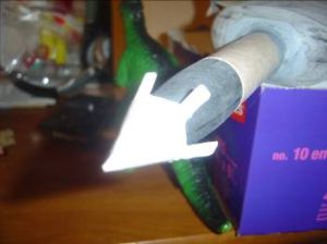
Take the body tube and slide it into the plastic fuselage. The aft end of the body tube should stick out of the aft end of the plastic fuselage approximately 0.5 inches. Mix up enough epoxy to create fillets around the fore and aft ends of the body tube. Apply the fillets and set the assembly aside and allow it to cure. Once the epoxy has cured, sand all epoxy fillets smooth.
Cut out the nosecone shroud from the supplied template on heavy card stock. Make the shroud curl by pulling it across an edge of a table. Cut a small strip from the card stock or paper and glue it to the bottom on one straight side of the shroud. Take the other side of the shroud and butt it up to the first side so that the shroud forms a cone. Set aside to dry. Next cut out the large shroud used for the “neck†and glue it together just as you did the nosecone shroud. Set aside to dry.
Using heavy grit sandpaper, sand the entire nosecone smooth. Make certain to smooth out the mold line that runs along the perimeter of the nosecone. Do not sand the shoulder. Sanding the plastic nosecone will ensure good adhesion of the nosecone shroud to the nosecone. After the nosecone is sanded, you can attach the nosecone shroud one of two ways. You can either use epoxy or you can use CA. Epoxy would be the better choice because it adds nose weight, and you have some time to adjust the shroud to get it centered and have even gaps across the circumference of the cone. Attach the nosecone shroud to the nosecone and place it on a scrap length of BT-50 body tube, if available. Otherwise, hang the nosecone from a piece of string and allow the CA or epoxy to cure.
Use scrap balsa to create the bridge and bridge platform. Glue two pieces of 3/16 inch balsa scrap together and allow to dry. Cut out the bridge platform using the supplied template. Wrap a piece of sandpaper to a pencil and sand a half-circle in the wide, front edge. The bridge will sit inside this half-circle. Glue to the nosecone using either CA or epoxy. The rear of the bridge platform should extend over the “neck†approximately ½ an inch.
Shape the balsa that you glued earlier into a cylinder with a rounded top, using heavy grit sandpaper. This will form the bridge. Trim the cylinder down to a length of approximately ¾ inch. Next, glue the cylinder between the nosecone shroud and the bridge platform using CA or epoxy. The bridge should sit inside the half-circle sanded into the bridge platform.
Sand the epoxy around the front of the fuselage smooth using heavy grit sandpaper. Spread wood glue around the outside of the neck 1/8 inch from the end where the nosecone will attach. Slide the neck shroud onto the neck and butt it up against the fuselage. Tack the shroud to the plastic fuselage using a couple of drops of CA. Mix up epoxy and spread epoxy over the rear edge of the shroud and blend the epoxy into the existing sanded epoxy. Set aside and allow epoxy and wood glues to cure.
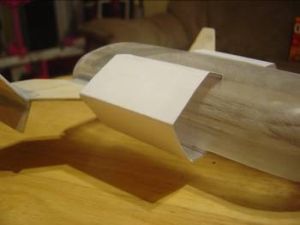
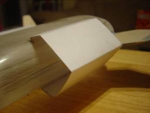
Cut out the two laser gun shrouds on the solid black lines then fold on the dotted lines. When folded, the shrouds should make a hexagon shape. Use a sharp hobby knife or a razor blade to cut a slit on the top and bottom of the fuselage. Slide one edge of the shroud into the slit on the top side and slide the other end of the shroud into the bottom slit. Do the same for the other shroud. Tack the shrouds in place using CA.
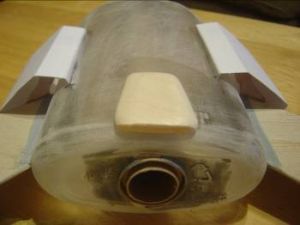
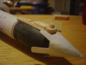
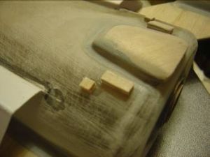
Use a scrap piece of thick balsa and cut it to approximately 1.5 x 0.75 inch rectangle. Round off all four corners of the rectangle then round down the top of the fore and aft ends of the rectangle. Place a piece of sandpaper rough side up onto the aft end of the fuselage. Place the rectangle onto the sandpaper and sand the bottom so it will conform to the shape of the fuselage. Center and attach the rectangle to the rear of the fuselage using CA.
Cut two more small rectangles, approximately ¼ x ½ inches from scrap balsa. Attach one small rectangle to each side of the larger rectangle made in the previous step using CA. The smaller rectangles should be ¼ inch from the larger rectangle. Cut two 1/8 inch squares from the same balsa material and attach to the fuselage 1/8 inch away from the small rectangles using CA.
Center the launch lug on the bottom of the fuselage and secure with CA or epoxy.
Slide the Kevlar® cord back through the engine mount and body tube and tie it to one end of the elastic cord. Tie the other end of the elastic to one of the attachment points on the nosecone. Loop the parachute shroud lines through the other attachment point on the nosecone. Pass the parachute through the shroud line loop and pull tight.
Finishing:
Start by sealing all the balsa using your preferred method. Prime the entire rocket with an automotive grade primer
that can be found at most automotive parts or home improvement stores. The automotive grade primer fills imperfections
very well and sands fairly easily.
Once the rocket has been primed, "dust" a light coat of flat black paint over the entire rocket to give it a "splattered" look. The flat black will show all the imperfections, help you keep track of where you have sanded, where you need to sand, and will ensure the surface is flat for the next priming session. Allow the primer to fully dry.
Sand all the flat black paint off with medium-coarse grit sandpaper, such as 220 grit. Re-prime the rocket and "dust" the rocket with flat black paint. After the primer has dried, sand all the flat black off again, using fine grit sandpaper, such as 400 or 600 grit.
Once the flat black has been sanded off, the rocket is ready to paint. Clean the entire rocket with glass cleaner, such as Windex. The glass cleaner has ammonia in it, which will not only remove the sanding dust, but it will also remove the oils left by your hands, which cause "fish eyes" in the paint. Paint the entire rocket light gray and allow to dry for several days.
Once the main color has fully cured, start applying the details like windows, vents, lettering, and the outline for the shuttle bay doors.
Decal templates can be downloaded here.
Flight:
This model will make it difficult to use the spin stability method because of the odd shaped fuselage, however, it
can be done. The CG should be directly in front of the laser shrouds. Prep the model as if you we going to launch it
using the largest motor you intend to use. Tie a long piece of string at the CG point and perform the spin test. Add
nose weight until the model spins correctly.
Recommended engines: Estes B4-4, B6-4, C6-3
 |
 |