Scratch Martian Madness Original Design / Scratch Built
Scratch - Martian Madness {Scratch}
Contributed by Bob Hart
| Manufacturer: | Scratch |
Note: This is a slightly condensed version of all the information that Bob has produced for his Level 3 project.
 Introduction
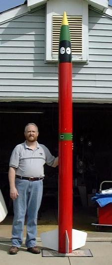
This project has consumed more time than I ever imagined, but it looks like I'm finally ready. I chose the name "Martian Madness" because several of us in the club are "Marvin the Martian" fans and I thought it would make for an interesting paint job. (This picture is the finished product - minus sneaker pinstriping on the fins).
Overview
This document is an overview of my Level Three Certification Project called “Martian Madness”. Documents, drawings and photos showing actual design and construction, parts list, recovery system, wiring schematic, electronics testing, flight profile, and a pre-flight checklist are also part of this documentation package. The design intent of this project is to design and build a vehicle of suitable size and strength to withstand the stresses of flight on a full “M” class motor and recover safely, yet still fly on an “L” class and “baby M” (M1315) motor for the actual certification flight. It will have altimeter-based dual ejection with redundancy provided by the use of two different brands and models of barometric altimeters; an Olsen FCP-M1 and an Adept P5. Overall vehicle dimensions are 7.5 inches in diameter and 11 feet tall. Liftoff weight with the M1315 is estimated to be 57.5 pounds and according to Rocksim calculations should reach an altitude of approximately 6,700 feet.
The major components of the rocket include a PML fiberglass nose cone, 7.5 inch diameter flexible phenolic tubing glassed with 6 ounce and 2 ounce fiberglass, and ¼ inch thick G10 fins. Six ounce fiberglass reinforcement was also added to the 98mm motor mount tube.
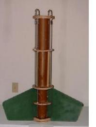
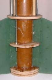
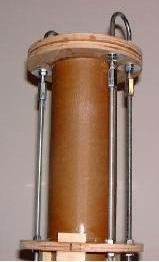
The altimeter bay uses a triangular altimeter support structure constructed of ¼ inch thick aircraft plywood with sealed areas at each end for connection of the electric match wire leads. Ejection charge safeing and arming, and power on/off will be controlled by 5 heavy -duty 3 pole double throw slide switches mounted vertically, with the on position towards the aft end of the rocket. Switch actuators are trimmed flush with the body to avoid accidental arming. Both altimeters have been flight tested in other rockets, and tests have been conducted to determine the required amount of black powder for the ejection charges and proper operation of the electronics under simulated flight conditions.
 Click Here for the Altimeter Bay Drawing in PDF format.
Click Here for the Altimeter Bay Schematics in PDF format.
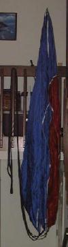
Recovery Package
The recovery system consists of a RocketMan R24D Pro-Experimental drogue parachute for the apogee deployment, and a RocketMan R18C Pro-Experimental parachute for main deployment which is rated for weights between 45 and 65 pounds. Vehicle sections and recovery devices are tied together with 2 inch wide seat belt strap and 1 inch tubular nylon. The drogue and main tubes are secured to the altimeter bay with 12 10-24 screws, with separation at the booster/drogue tube joint and at the main/nose cone joint. The nose cone will be secured for flight with shear pins.
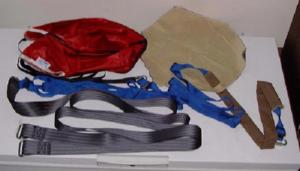
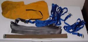
Next, documents the ground testing of the electronics systems including required charge size, pictures of the recovery harnesses and parachutes, and a wiring schematic for the electronics package. Picture 1 (below-left) shows the recovery harness and drogue parachute for apogee deployment. Picture 2 (right) is of the main parachute, and picture 3 (below-right) shows the recovery harness and deployment bag for main deployment.
Recovery System Ground Testing
Two separate ground tests were conducted on the recovery system: the first to determine the required amount of black powder to reliably deploy to main parachute as it would require the most due to volume and the use of a deployment bag, and the second to verify proper operation of the flight electronics and wiring under simulated flight conditions.
Ejection Charge Test
This test determined if an estimated quantity of black powder, based upon the experience of others with similar successful vehicles, would be adequate to completely eject the main recovery system. A similar test was not conducted for the drogue system, as the assumption is that with the reduce volume and smaller chute size, a slightly smaller amount than that required for safe ejection of the main chute would be adequate to the task.
After consulting with several successful level 3 flyers, my initial estimate for the required amount of black powder for the main was 5 grams. To test this estimate, a charge was prepared using the same canister that will be used for flight. To accurately simulate the flight preparation of the canister, 2 electric matches were installed, and the wire ends twisted together for safety. The prepared canister was then installed into the forward bulkhead, and both bulkhead plates were assembled onto the electronics bay. The main recovery system was prepared and installed into the main tube according to the same procedures outlined in the pre-flight checklist. The main tube was then assembled onto the electronics bay and the nose cone installed with shear pins.
The assembled sections were then placed on a test stand in our large back yard. Activation of the charge was through the use of a 9 volt battery. After giving a 5 second countdown the leads were connected to the battery setting of the charge. The results were the successful ejection of the nose cone and parachute bag. It was observed that the bag just made it out of the tube, and so the decision has been made to improve the margin by increasing the amount of powder to 6 grams. This should be more than adequate to achieve a safe result in the flight.
Ejection System Test
The purpose of this test was to verify that the ejection system wiring had been correctly installed and functional. To conduct this test, the switch harness from the Altimeter Bay was connected to the Altimeter frame, the P5 and M1 were connected to their respective harnesses, and electric matches connected to the output binding posts. Initially, a double pole double throw pushbutton momentary switch was going to be connected to each unit’s “G” switch and the tests run on both units simultaneously by pulling a vacuum on the entire bay, but this proved to be impractical. The solution was to test each unit individually, which would be adequate to verify proper wiring and operation.
After connecting all harnesses and the momentary pushbutton switch to simulate “G” switch activation, the arming switches on the Altimeter Bay were activated followed by switching on power. The unit under test was then observed to verify the correct power-on sequence. This was followed by pressing the pushbutton switch to simulate launch, and then applying a vacuum to the pressure sensor to simulate flight. The vacuum was held for a moment to cause the apogee event, and the corresponding match was observed to verify firing. The vacuum was then released and the main match observed. The results for both units were successful with matches firing in all instances and in the correct order.
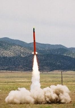 SUCCESSFUL LEVEL 3 FLIGHT!
March 24, 2001
NSL 2001
Rocket - Scratch Martian Madness
Weight - 57.5 lbs
Motor - Aerotech M1315
Altitude - ~5500 feet
In late 1999, the NAR finally felt that enough members had attained level 2 certification that it was decided to begin offering level 3 certification. In order to do this a "bootstrap" approach was agreed upon in that a group of experienced level 2 flyers were selected to form a "Level 3 Certification Committee" to which those wanting to certify would submit their designs for approval. A committee member must also observe the certification flight and sign the forms if the flight is successful. I, along with several others was selected to be on the committee, with the understanding that we must ourselves obtain certification within a certain time frame, which I did at NSL 2001.
 |
 |