| Construction Rating: | starstarstarstar_borderstar_border |
| Flight Rating: | starstarstar_borderstar_borderstar_border |
| Overall Rating: | starstarstar_borderstar_borderstar_border |
| Manufacturer: | Sunward Aerospace  |
Brief:
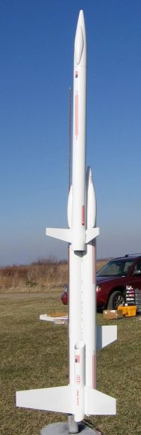
Sunward has come up with a very cool multi-tube futuristic design, however,
this kit will need minor modifications to be flight worthy. At 6.1 ounces
empty, it is more than 50% over the maximum recommended liftoff weight for a
C6-3 and trying to fly it on the recommended B4-2 for the first flight would
likely be the rocket's last.
Construction:
Parts arrived in good condition purchased from an online retailer:
- 3 BT-56 body tubes 18"
- 2 BT-50 tubes 8"
- 3 Sunward nose cones (plastic 56 with canopy)
- 18mm motor mount/centering rings/metal engine hook
- Laser cut balsa fins (3 sets of 2)
- Plastic chute, 18"
- rubber shock cord
- peel 'n' stick decals
Instructions are generally pretty good, as well as being written in both French and English. At times the illustrations and notes could be a bit confusing. Overall, this would probably be a skill level 2-2.5 kit, although with my recommended modifications it could be a skill level 3.
Motor mount assembly is straightforward, consisting of an 18mm tube, a couple of 20/56 centering rings, and a metal engine hook. The hook is a standard Estes-style rather than the L-bolt used in most other Sunward kits.
The body tubes are standard but need to be cut at a 45-degree angle for the styling of the kit. This is done through the use of wraparound templates to mark the cut lines. The template patterns used fairly thick lines (not consistent thickness) and the ends didn't quite meet wrapped around the tube, leaving me to think either I cut the "wrong" side of the template line, or the pattern is just plain wrong. After tinkering with the pattern a bit I still had uneven cuts, which took a bit of truing up using a sanding block.
The body "assembly" is built from a straight BT-56, with a pair of angled BT-56 tubes bonded side-to-side to the aft end and overlapping about 2". There are a couple of BT-50s trimmed at a 45-degree angle that go into the joints between the angled BT-56s at the aft end. The instructions didn't mention fillets and I felt a wimpy 2" overlap between the forward and aft tubes was a bit skimpy, so I applied generous white glue fillets (no doubt contributing to some extra weight on my build).
The fin instructions were very weak and if you're building this you'll need to read this carefully rather than the instructions. There are three sets of fins described as forward, upper, and lower. The parts list includes decent labels for which is which, however, these fins will appear to be backwards with the squared side as the leading edge and the trailing edge angled.
Step 6A of the instructions says "With lower fin: glue the two forward fins at right angles as shown...with remaining fins sand the root edges to a wedge as shown". There's an illustration of two generic (unlabeled) fins mounted side to side with a glue line between them, which basically looks like a standard glider 2-piece fin assembly, glued together to form a wing. One could easily infer that this was meant for the lower fin pieces. Wrong. What you're supposed to do is mount the FORWARD fins to the body tube at 90 degree angles to each other, though the location is in a seam between two tubes for ALL fins, so EVERY fin should be sanded to a wedge. Since the forward fin placement is covered in step 6F, I'd completely ignore 6A entirely except for sanding the wedges to the fin roots.
Upper and lower fins go in the various seams between the BT-56s and BT-50s at the aft end. No fin should be glued to any other fin, just to body tube seams.
The single 18mm motor mount goes into one of the two BT-56s. This will result in asymmetrical thrust but given the fin area and length of the tubes, this is probably not that critical. Still, given the bulky weight of this kit and that other empty BT-56 just sitting there--not to mention those BT-50s--I can't help wondering why this wasn't a 2-motor cluster from the start. I am certainly going to cluster mine using the second BT-56.
The shock cord is a paper tri-fold mounted into the BT-56 (the same one you chose for the motor mount hopefully). The other nose cones are glued into the other BT-56s. I chose to friction fit mine to allow for the potential clustering later, and make it easier to paint.
Finishing:
If you've followed the instructions carefully, you've cut out the part of the
page that includes the paint instructions and used it for your tri-fold shock
cord mount. I know that's what I did...
I applied two light coats of primer then sanded down a bit with wet/dry 400 grit sandpaper. I then finished with two coats of Krylon gloss white. Given the overlaps of the body tubes, it's much easier to paint this without the nose cones attached. Just paint them separately then attach them. I decided to stick with the all-white scheme rather than try to blend in a second color.
There are a few decent red stripe peel 'n' stick decals as well as some flags from US, Britain, and Canada. There's also a very undersized "Gravity Rider" sticker for the 41" long rocket.
Construction Rating: 3 out of 5
Flight:
After clearing out a pile of first flights for the day, I reluctantly grabbed
this one and put in the recommended C6-3 and called a heads up to all observers
to make sure everyone was standing up and mobile. I could not imagine even
trying a B4-2 in this rocket.
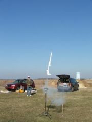
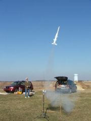
The motor did manage to lift it off the rod, however, it was still moving slow enough for the wind to blow it safely downrange (sideways) as it struggled to climb. The flight path reminded me of my many Estes Dude flights.
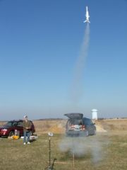
One guy trying to catch a flight shot used a "burst" feature on his digital camera that takes 3 consecutive shots. He managed to catch the Gravity Rider leaving the rod on 3 straight burst shots, underscoring how slowly this thing moved.
While I would not classify the flight as unstable since the apogee was less than 50 feet--I've flown MicroMaxx powered rockets higher than that--and the ejection was almost halfway back down, the flight was definitely unsafe.
Recovery:
The chute deployed but not in time to do any good. Fortunately, it didn't go
high enough to gain any descent speed and it landed in soft grass without
damage.
Flight Rating: 2 out of 5
Summary:
PROs: interesting design, futuristic and unusual.
CONs: horribly underpowered, should not be built/flown per the standard design.
In addition to making this a cluster of at least twin 18mm motors or better yet, twin 24mm motors, I would strongly recommend going with ducted ejection on this design. If you've ever built a Trident or Flis Grissom, you know how to do this. If you haven't built these, ducted ejection happens when you cut slots in two mating body tubes that overlap each other then make a strong seam with glue. The ejection gases from the lower tube go out the slot and into the slot of the upper tube, forcing the pressure out the forward/upper tube. In this design, you could cluster the lower BT-56s, duct the charges into the single forward BT-56, and pop one cone with one chute.
Overall Rating: 2 out of 5
Other Reviews
- Sunward Aerospace Gravity Rider By Preston Hoover (May 16, 2010)
Brief: The Sunward Aerospace Ltd kit the Gravity Rider is a kit for the future. The duel cluster motor, dovetail design and slanted end tube cuts give the rocket a sleek futuristic look. The kit boasts High Quality Laser Cut Balsa, Safe 18" parachute recovery, HUGE - Length 40" / 101cm , Wingspan 10 1/2" / 26cm , includes metal motor retaining clip , build as a cluster or ...
 |
 |
Flights
|
|
A.C. (May 18, 2006)
|
|
W.J.E. (March 13, 2006)