Upscale Break Away (YouBee) Fixes
By Roger Smith
2011-04-23
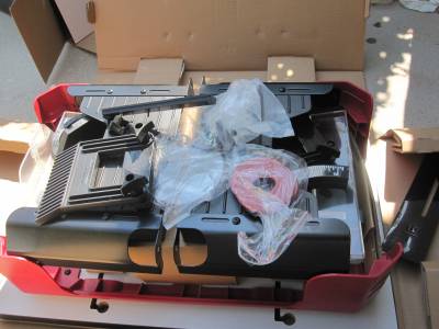
This isn't really a build, but a re-build. During its last flight at the TTRA launch, my Upscale Break Away ("YouBee") suffered some minor damage. It was a windy day and the rocket was flying horizontal when the ejection charge fired. The shock cord connecting the section with the electronics bay and main parachute separated from the rest of the rocket. The section with the parachute fell quickly to earth with the 'chute failing to properly deploy. The rest of the rocket did it's "Wacky Wiggler" thing pretty well, so it came in more gently.
Booster Section
2011-04-23
The post-mortem revealed a couple of zippers, a missing rail button, a slightly-crunched payload section, and a few other little dings.

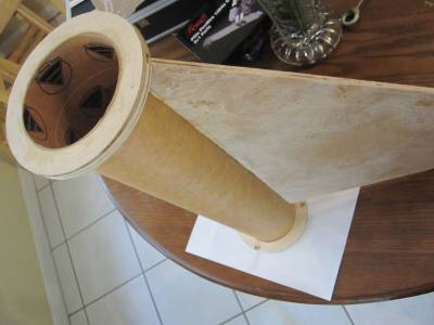
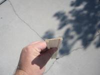
The coupler on the top of the booster had a pretty deep zipper - all the way through the coupler and into the body tube. The shock cord attachment was a wire loop and it left a zipper on the first flight also. So, obviously, a change in the way the shock cord attaches is needed. With the previous zipper and the new one, I decided to peel out the old coupler so that I could replace it. I used a cutting disc on my Dremel to make some diagonal cuts inside the coupler then pulled the coupler out of the body tube in sections. It took a while, but wasn't too hard to do.
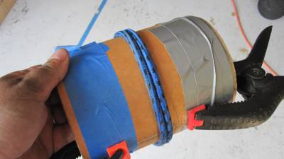
I didn't have a coupler of the right size, so I made one. I cut a couple of short pieces of body tube. I cut a slit out of each one - so that one would squeeze down to fit inside the body tube and the other so that it would squeeze down to fit inside the other tube. I put glue in the inside of the larger-diameter tube then inserted both tubes into a body tube - with the smaller diameter tub inside the larger diameter one and the slits I cut on opposite sides. I left the coupler in the body tube for a while to dry. Then I took it out and added some glue to the seem on the outside of the coupler. Then I tied it up as seen in the photo above and put clamps along the seam. This helps it to form a better coupler with less of a ridge along the seem.
Tomorrow, I'll glue the new coupler into the booster section.
Rail Buttons
2011-04-23
One of the rail buttons was missing from the booster. I don't think they were aligned exactly right. So, I decided make things a little better rather than just replace the missing guide.

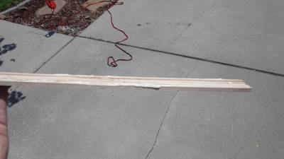
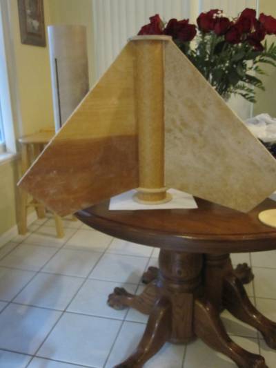
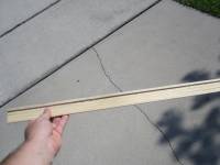
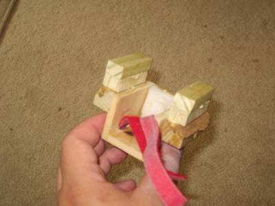
It's not a great photo .... What it is supposed to show is a piece of wood I cut and routed. It's a little less than two inches wide and about a quarter-inch thick. I routed a channel out of it so that it will sit flat against the booster section's body tube. I glued it to the side of the booster section, covering up the original rail button holes. I counter sunk a couple of screws to help hold it in place.

I also mixed some epoxy with filler and used it to fill the hole on the other side of the booster where a tree limb had impaled it at the end of its first flight.
On the list for tomorrow is attaching the rail buttons and sanding down the epoxy.
Zipper Fixes and Painting
2011-04-23
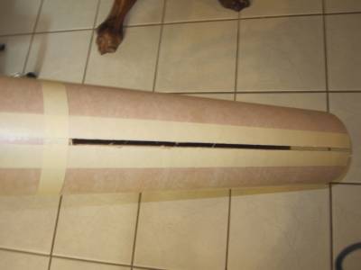
One of the other sections of the YouBee also had a pretty good zipper.
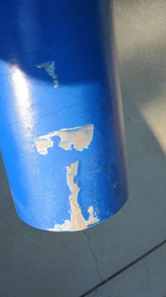
Since the YouBee uses standard cardbord tubes, the zipper was easy to fix. I spread white glue into the slit and on both sides. I let it dry then sanded the tube inside and out.
Another tube had dents at each end. I was able to flatten and sand them out. I applied some epoxy around the inside edges of the tubes to try to strengthen them a little.
I repainted a couple of the tubes and the nosecone. This marks the fourth time I've painted the rocket (which has only flown twice!).
I still have the zippers in the booster to fix, but I'll do that tomorrow after installing the new coupler.

More Fixing and Painting ...
2011-04-25
Yesterday, I got a lot done fixing the YouBee, but I didn't finish.
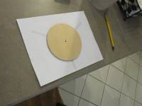
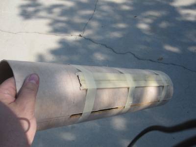
First of all, I unwrapped the homemade coupler.

Ah! A work of art! :-)
I glued the new coupler into the top of the booster section. Then I painted the booster.
I found that the section of tubing that held the main parachute was crinkled a little. It wouldn't have been too hard to fix, but it was easier to just replace it. So, I started to paint a section red and orange. Also, I disassembled the electronics bay and discovered that it must have hit the ground pretty hard. The altimeter sled had broken free of the threaded rods and the battery had come out of its holder.
One of the problems with the last flight is that the bulkheads on each end of the electronics bay got pulled out of place. I had the shock cords attached to a U-bolt mounted off-center in the bulkheads. To prevent the problem from happening again, I'm replacing the wing nuts on each end of the central threaded rod through the electronics bay with eyenuts. The shock cords will be attached to the eyenuts.
I also repainted the electronics bay.
I think I need to buy some more orange paint.
I don't have any photos, but I also attached a loop of a wide nylon strap to the top of the 98mm to 54mm motor adapter i made for the rocket. I'll use either the strap, or an eyebolt on top of the motor, as the place to attach the shock cord. This should eliminate the zipper I got on the booster during each of the two flights.
Let's see ... I still need to rebuild the altimeter sled, finish painting the new main section, and replace the shock cords. Oh ... yes, and I need to remember to add the rail buttons!
It's been a while ....
2011-07-28
And I haven't remembered to update this build thread ....
No photos, yet, but I tested the altimeter using a simple tester built from a Mason jar and a syringe. The altimeter appears to be working fine.
The rail buttons have been added. I bought a segment of 1515 extrusion from McMaster-Carr and used it to ensure that the rail buttons are lined up right. The rocket now slides easily on the rail with much less friction than before.
I'm considering adding a camera mount near the rear of the rocket to get video looking up the rocket - mainly to try to catch the "Wacky Wiggler" part of the descent. If I do that I might also add another down-looking camera since the one at the top of the rocket doesn't capture any of the flame from the rocket.
Deja Vu All Over Again
2012-05-20
After rebuilding the YouBee as described above, I flew it at NEFAR's Bunnell Blast last November. The flight was pretty good ... at least the up part went well. At apogee, the rocket split apart, but not as planned. I had forgotten to attach one end of one section of the recovery harness. So, the back half of the rocket came down without a parachute. It wasn't too bad since it fell horizontal, but one of the fins became loose at the root edge. I was able to re-glue it. But, it ended up a little out of alignment. I doubt anyone else would notice it, but it bugged me. So, I took it as a sign that I should rebuild the fin unit.
I may have been looking for an excuse since the original fins weren't exactly the same shape as the Odd'l Rockets Break Away and, at 1/2" thick, they looked a little clunky.
So, I decided to start by making fins about 1/4" thick. I started with thin plywood from the local Home Depot. Using a set of fins from a Break Away kit, I cut out a set of fins of the right shape and about 5 1/2 times as large.
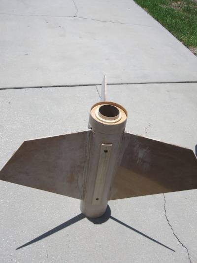
The new fins are the right shape and are a little larger than the original YouBee fins.
I fiberglassed each side of each fin. I spread the cloth over a side of a fin and spread expoxy over it. I covered it with wax paper and placed a flat board on top and weights on top of the board. After the epoxy dried, I used a table saw and belt sander to the edges of each fin.
One side of each fin turned out really nice - flat and smooth. The other side, however, was filled with ridges. I'm not sure what caused the problem. But, the fix wasn't too hard. I mixed some 410 Microlight Filler with epoxy and spread it on the bad side of each fin. After it dried, I sanded the fins using a electric hand sander. It created a lot of dust and used several sheets of sandpaper. But, after a while, I had a set of thin, strong, and smooth fins!

Centering Rings
2012-05-20
I used the wood I bought for the fins to make centering rings. At first I tried to kill myself.
The jig I built for an old router I have can't cut smaller than 8" circles. The circle cutter I have cuts up to 5" diameter cuts. The inside diameter of the YouBee is almost 5 1/2".
What the heck. I decided to try using the circle cutter in my drill press to cut the rings. What difference is an extra 1/2" going to make?
So, I attached the cutters to the very limits of the tool. Sensing some danger, I held a piece of plywood in front of me as I turned on the drill press.
Sure enough, one of the cutters flew off, bounced off the piece of wood, and hid itself somewhere under something in the garage.
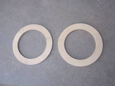
Coming to my senses, and taking advantage of the excuse to buy new tools, I ordered a Dewalt 618 Plunge Router and a Jasper Circle Jig from Amazon.com. When they arrived, I was able to cut out more centering rings than I need in just a few minutes. It was so easy, I got carried away.
I cut the rings so that the outside diameter was a little too large and the inside diameter was a little too small. Then I used a sanding bit in my Dremel rotary tool to shave the rings to the right sizes.
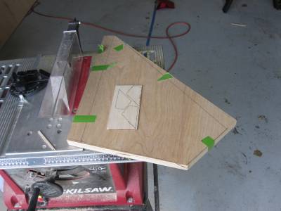
Having cut out more rings than I really needed, I decided to try something different. I used the Fin Guide Tool at PayloadBay.com to create a template for the YouBee's fins. I used it to cut one of the rings into thirds - cutting away the areas where the fins would go. I glued the peices to one of the other centering rings. This created grooves in the upper centering ring for the top of the fin tabs.
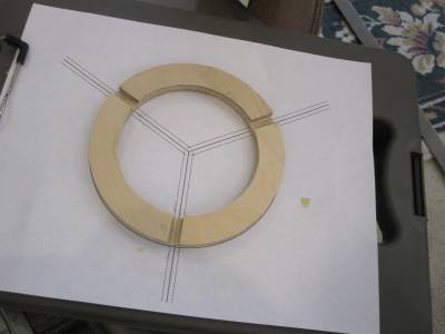
I cut notches in the outside of the lower centering ring because I didn't put a straight tab on the bottom of the fins.
I actually made the grooves and notches a little too big, so they ended up not really helping to align the fins. But, I think the technique will work. In the future, I'll make the grooves a little too small and widen them with the Dremel to the exact size needed.

Fin Assembly
2012-05-21
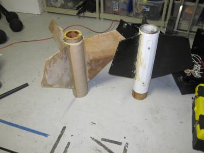
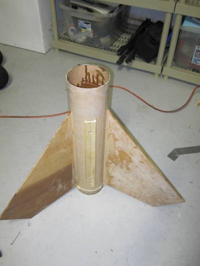
The next step was pretty straight-forward. I used wood glue to glue the centering ring with the grooves to one end of the motor tube. Then I glued each fin, one at a time, to the motor tube.
I glued the ring with the notches to the tube at the bottom of the fins. Then I added another ring at the other end of the motor tube. The rear ring is all the way at the end of the tube because I plan to install an Aeropack 98mm retainter on it. The 98mm retainer has a flange which requires the rear ring to be at the end of the tube.
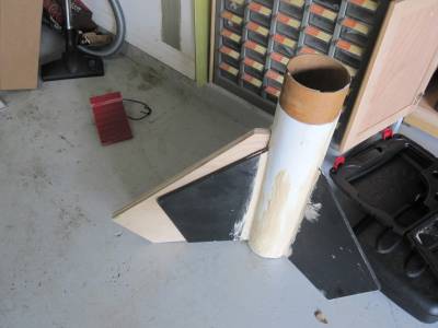
I cut a short piece of body tube just the right length to fit between the two rear centering rings. I cut a section out of it so that it could be squished down to the diameter of a coupler tube. I glued it into the space between the two rear rings.
Once the wood glue had dried, I took the assembly outside and applied strips of fiberglass along the root edges of the fins to securely attach them to the body tube. I don't have photos of this because it's hard to take pictures while wearing nitrile gloves covered with epoxy. Plus, it was so messy that I didn't think it was appropriate for public viewing.

Fin Slots
2012-05-21
Next, I cut slots in the body tube for the fins. I used ... yes ... the PayloadBay.com Fin Guide to mark spots on the bottom of the tube. To do this, I used a little trick. I taped a centering ring to the guide. It's easier to center the ring in the template and the ring holds the tube steady while you mark it.

After marking the spots for the slots, I used an length of angle-shaped aluminum to extend the lines up the tube. Then I outlined the locations for the slots with masking tape.
I used a razor knife to cut out the slots. And, well, that was about it.
Rail Guide Attachment
2012-05-21
When I rebuilt the fin section of the YouBee the first time, I had to repair the spots where the rail buttons attached. I came up with a method that worked well, so I decided to use it on the new fin section.
I needed a piece of 1/4" thick, 1 1/2" wide wood. I could have cut it from the wood I used for the fins and centering rings, but, it was close to lunch time and the hot dog cart in front of Lowes serves really good Italian sausages. So, I went to Lowes for the piece of wood.
While I was there I picked up a router table for the new router. The box said "pre-assembled" which, I guess, means "some assembly required."

I assembled the pre-assembled router table and used it to route out the middle of the new piece of wood.
I glued the strip of wood to the body tube centered between two fin slots.
After the glue dried, I drilled two 1/2" diameter holes, one near the top of the wood strip and one near the bottom. After the fin assembly is complete, I'll insert well nuts into the holes then screw in the rail buttons.
It's Starting to Look Like Something
2012-05-23
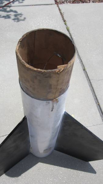
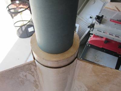
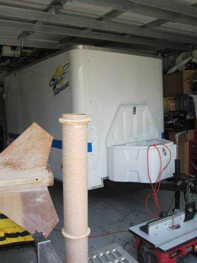
I slid the body tube over the fin unit and glued it place with epoxy. I used masking tape to hold the end tight against centering ring. What you can't see in the photo is that I attached a u-bolt to the upper centering ring for attachment of the recovery system (for motors that don't have a threaded front enclosure).

Then, I mixed some microlight filler into epoxy to form a thick paste which I used to fillet the fins and edges of the rail guide board thingy.
I still need to add some more epoxy fillets and sand the whole thing down. But, it's finally looking like the back end of a rocket! And, I can tell it's going to look a lot nicer than the original fin set.
Crisis! / Crisis Averted!
2012-06-10
"Crisis Averted" - that would be a cool name for a rocket!
Anyway ... I ordered an Aeropak 98mm retainer set for the new YouBee. When it arrived, I decided to see how it fitted on the rocket.
I picked up a 4" coupler to put in the motor tube to use to align the retainer. And, I discovered a problem ....
The coupler did not fit into the motor tube! I had used a coupler instead of a motor tube. Ugh!
Okay ... I don't own any 98mm motors. And I'm not planning on flying the YouBee on a 98mm motor. So ...
I made a (slightly less than) 98mm to 75mm adapter and glued it into the 98mm coupler. The adapter is basically the same as a LOC/Precision 98-to-75mm adapter, but with slightly smaller centering rings.
So, I now have a rocket with a 75mm motor mount.

Electronics Bay and Camera Section
2012-06-15
I replaced the e-bay with one I built from a LOC/Precision electronics bay. It turned out that the long sled I built to hold the altimeter in the original YouBee's e-bay was easily cut down to fit into the shorter LOC e-bay. So, all I had to do was glue new tubes to the back of the sled to slide over the e-bay's threaded rods.

Just for the heck of it, I covered the short bit of body tube around the e-bay with some of the reflective blue tape left over from decorating the JonRocket.com trailer.
For the original YouBee, I built a long electronics bay that held the altimeter and also held a video camera. One problem was that the camera stuck too far out of the rocket. You couldn't see any of the rocket in the videos which I don't think is as interesting as when you can see some of the rocket and the motor's flame and exhaust. So, one goal of the rebuild is to make camera sit deeper into the rocket. I couldn't do this in the original electronics bay because the altimeter sled was in the way. So, in the new YouBee, I decided to put the camera in a separate section.
The camera section is basically a short length of tube with the camera mount in the middle. A bulkhead just above the camera provides a place to connect the recovery system. Above the bulkhead is a connector that attaches to the upper section of the rocket (which contains the main parachute.
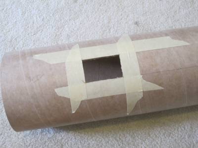
I started by cutting out the hole for the camera in the side of the body tube. I used an angled piece of metal to draw straight lines on the tube and framed the area to cut out with masking tape. I used a razor knife to carefully cut out the square hole.
I ripped the camera mount out of the old YouBee's electronics bay and glued some blocks of wood to it to make it sit deeper in the rocket.
I glued the mount into the body tube under the hole.
I created a bulkhead to fit in the tube and coated it with epoxy to help protect it from the ejection charge residue.
I drilled holes in the bulkhead for a u-bolt and to provide a way for the leads from the ejection charge to get to the electronics bay.
I added the u-bolt then glued the bulkhead and a coupler into the top of the camera section tube.
For flight, the camera section will be attached to the electronics bay using screws and the upper section of the rocket will be attached to the camera section with screws.
Painting
2012-06-27
No photos yet, but I started painting the fin section. Actually, I thought I had finished painting it. But, the glossy paint made the imperfections obvious in the finsihing job I did. So, I'm going to sand it down and try again. I'll fill some of the more obvious problems then use a heavy primer on it. Then I'll sand it some more. Then I'll mask and paint it again.
Wooo Hooo!!!
2012-11-04
It's been a while since the last update because it has been a while since I've done much work on the YouBee. But, NEFAR's Bunnell Blast is next weekend and I want to fly the YouBee. So, I spent all day today working on the rocket.
I ... for about the twelfth time .. primed and sanded then painted the fins. I'm still not real happy with the finish on them but ... I have to say the fin section looks much nicer than the original.
Today, I attached the rail buttons to the fin section and the blue section. I used well nuts which is a very easy way to secure them. Combined with the wooden shim pieces that I attached to the fin section and blue section, the buttuns ended up perfectly aligned which I confirmed using a length of 1515 extrusion I keep in the garage.
I started assembly of the recovery system, hooking up the parachute and attaching the top section to the electronics bay. I went ahead and created the ejection charge and hooked i up to the altimeter. And, I inserted the shear pins to hold the nose cone in place. So, the top half of the rocket is ready to fly.
I assembled the Aerotech K480 motor and attached an Aeropack 5475 adapter to it. It slides nicely into the motor mount and is help in by the Aeropack retainer. So the very bottom of the rocket is ready to fly.
I just need to do some work on the middle of the rocket!

Another Photo
2012-11-04
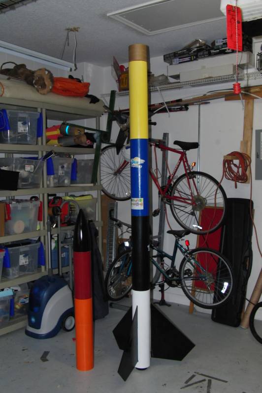
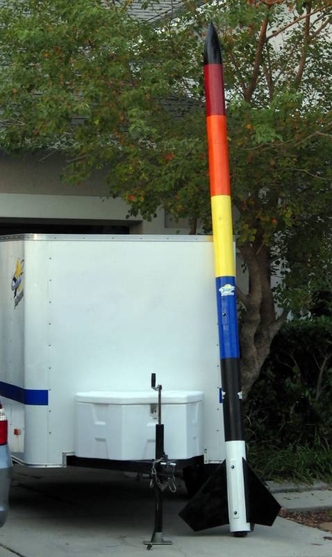
Here's another photo of the "new" YouBee.

 |
 |