U.S. Rockets Stiletto
U.S. Rockets - Stiletto {Kit} (1039, K-39) [1979-]
Contributed by Lance Alligood
| Construction Rating: | starstarstarstarstar |
| Flight Rating: | starstarstarstarstar |
| Overall Rating: | starstarstarstarstar |
| Manufacturer: | U.S. Rockets  |
Brief:
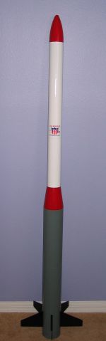
The U.S. Rockets (USR) Stiletto is a lightweight, durable, and versatile high
power rocket with a unique look and provides a challenging build for the
advanced rocketeer. Key features are the transition, which is a shroud formed
by the body tube and the Interchange MountsTM
allowing it to be flown on one 38mm motor, one 29mm motor, or four 24mm motors.
Motor mounts for one 54mm motor or three 29mm motors are available from USR as
well. The builder must supply their own parachute for recovery.
Construction:
The kit has the following parts:
- 2 BT-39.17.lw body tubes
- 2 BT-26.18 body tubes
- 1 TC-39-3 tube coupler
- 1 TC-26-6 tube coupler
- 1 BT-26.12 motor tube
- 1 large balsa nose cone (5.5" long)
- 5 match sanded 1/8" birch plywood fins
- 4 CR-39.26 centering rings
- 1 EB-26 baffle bulkhead
- 1 4" coupler and bulkhead plate
- 1 large screw eye
- 1 9' x 1/2" elastic shock cord
- 1 large paper tri-fold mount
- 2 1/2" launch lugs
- 2 1/4" launch lugs
- 1x38mm motor mount assembly, consisting of:
- 1 38mm tube
- 1 2.6" coupler tube
- 2 2.6" x 38mm centering rings
- 1x29mm motor mount assembly, consisting of:
- 1 29mm tube
- 1 2.6" coupler tube
- 2 2.6" x 29mm centering rings
- 4x24mm motor mount assembly, consisting of:
- 4 24mm tubes
- 1 2.6" cluster bulkhead
- Peel 'n' stick decal sheet
- Instruction manual
- Transition pattern sheet
- Advanced Information Report (AIR) #3 -- Motor Installation, Clustering, and Staging
- Advanced Information Report (AIR) #4 -- ACE Fugue Shroud Method

First impression is that I was impressed by the quantity of the parts upon opening the large box. The large body tubes did have dents in the ends of each one but nothing serious enough to warrant replacement. These flaws were either cut out when making the transition shroud or shaped back into round when coupled together. All other parts were in excellent shape. While the number of parts may be initially daunting, a sizable portion are for the interchangeable motor mounts.
The instructions are acceptable for walking the advanced builder easily through the assembly. I however chose to somewhat jump around through the steps but still maintained a logical build order. Aliphatic resin (yellow wood glue) was used for construction except where noted. All body tubes were sanded with 220 grit sandpaper where glue was applied as well.
 I started
by building the motor mounts first. Some minor sanding was needed for a smooth
but not too tight fit of the centering rings onto the 38mm and 29mm motor
tubes. I glued and filleted one centering ring flush onto the end of each tube.
The outer diameter (OD) of the centering rings are the same OD as the coupler,
so the coupler was glued with one end resting against the CR. The remaining CR
was glued onto the other end of the coupler and a fillet around the 29mm and
38mm motor tubes to secure the entire assembly.
I started
by building the motor mounts first. Some minor sanding was needed for a smooth
but not too tight fit of the centering rings onto the 38mm and 29mm motor
tubes. I glued and filleted one centering ring flush onto the end of each tube.
The outer diameter (OD) of the centering rings are the same OD as the coupler,
so the coupler was glued with one end resting against the CR. The remaining CR
was glued onto the other end of the coupler and a fillet around the 29mm and
38mm motor tubes to secure the entire assembly.
The 4x24mm motor mount was more simple, yet more complex at the same time. First I glued the tubes in pairs and let them dry on a flat surface to ensure that they were straight. Once the pairs were dry, I glued them together to form a square pattern. These 4 tubes were quite a bit smaller in diameter (even at their widest point) than the 2.6" host mount tube. To assist in centering the tubes onto the cluster bulkhead plate, I raided my personal tube supply for some 2.6" medium thickness coupler tubing. I sliced off a 1/2" ring and glued it onto the cluster bulkhead. The motor tubes where then glued flush against the bulkhead with the coupler ring providing some additional surface area (not to mention a better seal to stop any potential ejection charge leakage) for the tubes to be glued to.
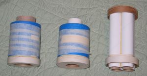
The instructions recommend that you build thrust rings on the OD of all 3 motor assemblies with masking tape. Realizing that was going to use a LOT of masking tape, I brainstormed for a moment. I came up with slicing three 1/2" rings from the end of the 2.6" diameter Host MountTM tube. Each of these rings were glued onto the end of each motor assembly. This took a lot less time and tape for a more durable and reliable solution. Masking tape was added as necessary for a proper snug fit of each assembly into the rocket.
 With the
motor assemblies complete, it was time to begin construction of the rocket
itself. Centering rings are glued and filleted onto the 2.7" Host Mount
tube. The instructions have you do it 1" from each end but I put them only
1/2". I made this decision because the 4" tubing is on the thin side
for a high power rocket and the fins are mounted far enough forward that the
aft end of the tubing is all but assured to touchdown first and therefore be
more likely to become dented and dinged up.
With the
motor assemblies complete, it was time to begin construction of the rocket
itself. Centering rings are glued and filleted onto the 2.7" Host Mount
tube. The instructions have you do it 1" from each end but I put them only
1/2". I made this decision because the 4" tubing is on the thin side
for a high power rocket and the fins are mounted far enough forward that the
aft end of the tubing is all but assured to touchdown first and therefore be
more likely to become dented and dinged up.
On the subject of being dented, both of the 4" tubes had been the recipients of some minor shipping damage resulting in 1/2" slices needing to be removed. I kept one of the rings and after gluing the entire Host Mount assembly flush with the end of one tube, I removed ~1/8" sliver so that it would fit inside the aft end of the rocket. This effectively doubled the thickness of the 4" tubing and hopefully providing further dent resistance upon impact. With that dry, I glued the 4" coupler into the forward end of the tube.
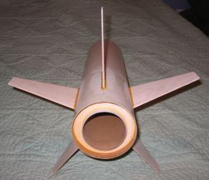
The shroud marking template also acts as a fin marking guide. I marked the location off for the fins and added marks for where I planned to drill the tube for rail buttons. With the fin locations carefully marked on the tubing, I began one of my favorite tasks: slot cutting. I prefer to use a razor blade utility knife as it has a thicker and longer lasting blade yet is just as sharp as a X-Acto knife. The fins were rounded on the leading and trailing edges, trimmed slightly at the root edge (to minimize the length of the fin slots to be cut), attached, and filleted into place with yellow wood glue. This sub-assembly was set aside for the time being.
I moved on to the forward end of the rocket. The instructions have the rocket built for nose cone ejection, which means having to finish and transport the rocket at full length. While I could handle the transportation part OK, I absolutely loathe having to paint any rocket parts greater than 36" in length. I would have to make a slight modification here... Instead of attaching the screw eye into the balsa nose cone, I cut a bulkhead from 1/8" birch ply. This was glued and filleted into one end of the mega-heavy duty 6" long 2.7" coupler. (I should also mention that this coupler would be ideal for using as an altimeter bay.) The coupler was glued into one of the 18" long 2.7" tubes. I left the nose cone to be friction fit into the newly created payload tube.
 Now the fun
really begins as it was time to make the transition. First the centering rings
needed some sanding to fit onto and into the tubes easily. While not exactly my
favorite thing to do, I'd still rather have to sand parts to fit than have them
flopping around loosely. The centering rings are mounted 1/2" and 4"
from one end of the 2.7" tubing. A baffle bulkhead is also glued inside
the same end of the tubing as the CRs. This baffle does not provide complete
protection from any ejection charge (duly noted in the instructions as well)
but serves as a method of keeping the recovery equipment from getting caught
inside the larger diameter tubing aft of the transition.
Now the fun
really begins as it was time to make the transition. First the centering rings
needed some sanding to fit onto and into the tubes easily. While not exactly my
favorite thing to do, I'd still rather have to sand parts to fit than have them
flopping around loosely. The centering rings are mounted 1/2" and 4"
from one end of the 2.7" tubing. A baffle bulkhead is also glued inside
the same end of the tubing as the CRs. This baffle does not provide complete
protection from any ejection charge (duly noted in the instructions as well)
but serves as a method of keeping the recovery equipment from getting caught
inside the larger diameter tubing aft of the transition.
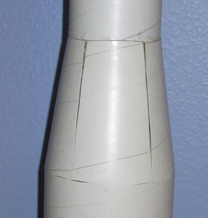
The template used for marking the fins is now wrapped around the second piece of 4" diameter tubing. Triangles are cut out from the tube along with short relief cuts at the points so that the tubing will gently fold into place. This technique is described in plenty of detail in the AIR #4 report and again in the instructions. With all cuts made, the smaller tube is glued into position inside the larger tubing. I found that some trial and error is required from this point on. Each of the five flaps that make up the shroud need to fold with as little creasing as possible. The relief cuts needed to be lengthened by ~3/16" (for a total length of ~5/8") and widened (to about 2mm). Keep in mind that this is just a shroud that covers the actual components (read: centering rings) handling the load bearing forces.
I used polyurethane glue to attach the shroud flaps to the smaller diameter airframe. Polyurethane glue expands as it cures so it will fill in small gaps, which is what is needed here. Flaps were glued on one at a time and covered with a couple pieces of masking tape to ensure that the flaps do not separate from the tubing, not to mention form a "bowl" for the polyurethane glue to stay in while drying. There are small gaps between each of the flaps that needed to be filled. I like the clean lines of the transition so I filled them with more polyurethane glue. Aside from filling the gaps, it also strengthened the shroud considerably without adding any significant weight. Sanding and filling with diluted Elmer's Fill 'n' Finish are required for a smooth, seamless transition. It took a few applications of F'n'F and sanding to get it ready for paint. More adventurous folks might do something like cut some thin birch ply or basswood and wedge them in the gaps like little canard fins to further enhance the cool look of the design.
With all 3 sections complete, all that was left was to glue the motor mount/fin can section to the transition section and glue the heavy duty elastic shock cord with tri-fold mount into the airframe. (I actually waited to do this after finishing.) I tied a small loop into the shock cord for assisting with chute attachment and then tied the end of the shock cord to the screw eye. It is worth nothing that USR also suggests friction fitting the aft and middle sections together then using a wrap of electrical tape over the seam (for cosmetic reasons) to increase the portability of the rocket as well. I tested this technique to verify that it would work. Not only would electrical tape be acceptable but so would low tack blue painter's masking tape, although it doesn't look as attractive as the electrical tape. Yet another plus in the versatility of the Stiletto design!
PROs:
- Fantastic looking, lightweight, high performance rocket.
- Comes with adapters for 3 different motor configurations. (And more adapters are available separately!)
- Highly portable and modular construction and design.
CONs:
- Fabricating the transition is best left to advanced builders.
Finishing:
There were no surprises during the finishing process. I kept the rocket in 3
main parts so it made them easier to be handled while being filled, sanded, and
primed. Filling and smoothing of the fins (including fillets) and nose cone
were done first though with diluted Elmer's Fill 'n' Finish and 320 grit
sandpaper. I have praised USR in the past for their smooth tubes and the
Stiletto was no exception to that compliment. A couple coats of Krylon primer
and then time for color. No color scheme is recommended, so I came up with my
own. Red, white, gray, and black (all Krylon colors) were chosen to form a
traditional, almost retro paint scheme. Very small peel 'n' stick decals were
included (compared to the size of the rocket). I chose to only use a single
large U.S. Rockets shield logo.
Construction Rating: 5 out of 5

Flight:
Prepping the Stiletto for flight is easy and provides some unique advantages
over almost every other rocket in my fleet. Motor retention is made easy,
particularly with RMS casings. I am a fan of masking tape friction fit but I
actually load the built motor casing into the Interchange MountTM first, then wrap masking tape around the
casing just forward of the motor tube, which would prevent it from
kicking during ejection. Lastly, the entire mount with motor is friction fit
into the rocket. (For other folks not comfortable with friction fit retention,
you could use a simple metal clip/screw/t-nut method to retain the mount in the
rocket airframe.)
I wanted to do a shakedown flight on a H180W-M and if it proved to be successful, follow it up with a Pro38 I205. With Stiletto loaded up on the rail, the countdown started. Ignition happened instantly and the rocket didn't hesitate to race skyward. Boost was impressive for such a large diameter rocket. Even with the 5-10mph winds at ground level, Stiletto showed that it was much calmer higher up as it maintained a near vertical trajectory. Impressive! I was getting really excited as I spotted the chute come out thinking how the I205 was really going to put it up there!
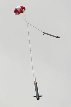
Recovery:
There is plenty of room for the shock cord and parachute in the forward
airframe section. You are warned in the instruction manual that the baffle will
only prevent some ejection particles from damaging the recovery devices, so
wadding should still be used. I dropped a big handful of dog barf cellulose
wadding before packing in the chute. The Stiletto does not come with a
parachute so I have a 30" PML chute from my Phobos and I used a 1/8"
quicklink to hook it to the shock cord. I also used one of my rocket beepers to
aid in recovery. There was plenty of room for the wadding, shock cord, beeper,
and nylon parachute.
 On its
first flight, Stiletto must have still had quite a bit of momentum at the time
of ejection. It seemed that the payload tube came back and hit right on one of
the fin leading edges hard enough to cleanly remove the fin from the airframe.
There will be a second flight but it was not going to be the same day at the
first flight... The PML 30" chute that I borrowed from my Phobos was
exactly the right size chute though bringing it down with minimal drift and at
a safe descent rate. I should also mention that I need to work on the friction
fit method for the host mount. Late in recovery the mount along with my casing
worked their way free and recovered separately. Good thing that someone in the
crowd noticed! While I recovered the rocket, they went out of their way to
retrieve the mount and casing for me. I generously thanked them for that!
On its
first flight, Stiletto must have still had quite a bit of momentum at the time
of ejection. It seemed that the payload tube came back and hit right on one of
the fin leading edges hard enough to cleanly remove the fin from the airframe.
There will be a second flight but it was not going to be the same day at the
first flight... The PML 30" chute that I borrowed from my Phobos was
exactly the right size chute though bringing it down with minimal drift and at
a safe descent rate. I should also mention that I need to work on the friction
fit method for the host mount. Late in recovery the mount along with my casing
worked their way free and recovered separately. Good thing that someone in the
crowd noticed! While I recovered the rocket, they went out of their way to
retrieve the mount and casing for me. I generously thanked them for that!
When packing up Stiletto for the ride home, I removed the black electrical tape holding the aft and middle sections together. It did peel off some of the paint on the middle section which had been painted several days after the aft section. (Thankfully another application of tape will easily cover it up.) The electrical tape worked extremely well during flight and I endorse using this technique with Stiletto. Just make sure that you allow plenty of time for your paint to dry before applying it for the first time!
Flight Rating: 5 out of 5
Summary:
For the advanced rocketeer in search of a unique rocket for their Level 2
certification, this would be a good choice. I think the shroud technique would
be too advanced for most folks going for their Level 1 certification. Once the
builder is familiar with fabricating the transition shroud though, the Stiletto
is a superb flyer on single motors from Gs to Js and I look forward to getting
my hands on a stockpile of Estes D12s for a clustered flight! (USR even claims
that Stiletto can safely handle drop staged D12 flights!) This kit is also a
great choice for someone wanting to experiment with mid and high power
clustering. Such versatility for just one rocket!
Overall Rating: 5 out of 5
 |
 |
Flights
|
|
|
|
U.S.R. (March 2, 2005)