Modification Yellow Jacket
Modification - Yellow Jacket {Modification} (7005)
Contributed by Jim Bassham
| Manufacturer: | Modification |
 Brief:
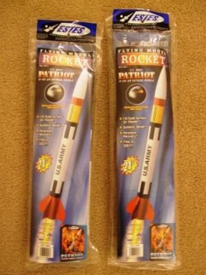
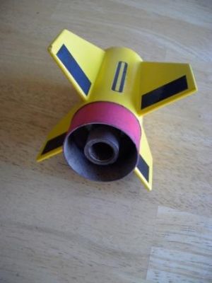
The Yellow Jacket is a two-stage rocket constructed solely from the parts of two Estes 1:10 scale Patriot kits. The rocket uses direct coupling of the motors with an engine block above and below the motors to aid in pulling the lower stage off cleanly as described in "The Handbook of Model Rocketry".
Construction:
The two kits contain:
- 4 White (BT60) body tubes, 6-5/8" Long
- 2 Yellow (BT60) body tubes, 3-¼" long (Only one needed)
- 2 Nose cones (only one used)
- 2 Blue engine mount Tubes
- 4 Red couplers, 1-½" long (Three used)
- 2 Green engine blocks
- 2 Centering ring cards
- 2 Parachutes (one used)
- 2 Shock cords
- 2 Launch lugs (one used)
- 2 Sheets of die-cut fins
- 4 Decal sheets
- 2 Mylar retainer rings (not used)
- 2 Engine hooks (not used)
Build instructions, including finishing:
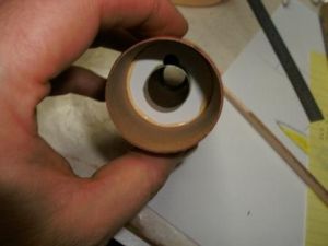
- Cut the two blue motor tubes to 2-9/16" long.
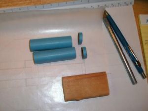
- Glue the green motor blocks flush with the ends of the blue tubes.
 Mark each tube 3/8" from the open end.
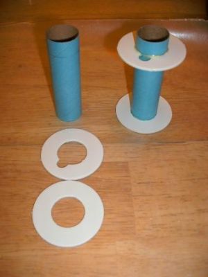
 - Glue the solid centering rings 1/16" from the blocked end of each tube.
- Glue the notched ring at the 3/8" mark at the other end.
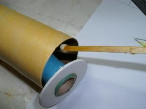
- Using a stick, apply a bead of glue 2-¾" inside one of the white body tubes.
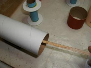
- Insert the motor mount part way and apply a second band of glue ¾ inside the tube.
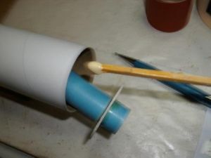
- Slide the motor mount into place, making sure the rear centering ring is ¾" from the rear of the body tube.
- Once the assembly is completely dry, insert a coupler until it is flush with the motor mount. Make sure it slides freely. Mark the coupler.
- Apply glue to the inside of one of the yellow body tubes.
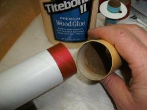
- Slide the yellow body tube onto the coupler, and quickly remove it. Try not to let the coupler shift.
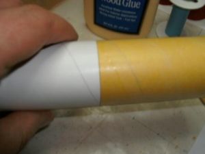
The mark you made in step 8 should not be showing.
- The coupler should have pushed up a bead of glue inside the yellow tube.

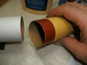
Quickly, insert the other motor mount's open end with the notched centering ring part way into the body tube. Apply a bead of glue with a stick in front of the lower ring
and slide the motor mount all the way into the tube until it is in contact with the coupler.
- The blocked end of the motor mount should be facing the bottom of the rocket, opposite the coupler.
This will allow the first stage motor to push the booster off the rocket at staging. - Fillet all the motor mount centering rings.
- Gather the white body tube with the motor mount, two red couplers and two more white tubes.

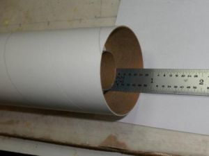
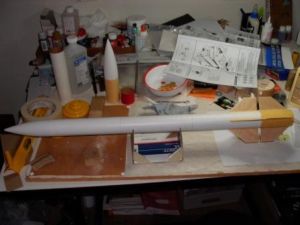
Mark the two red couplers at the mid-point (3/4") and assemble the sustainer body by gluing the three white tubes together with the couplers. The two stage bodies will now look like photo 17.
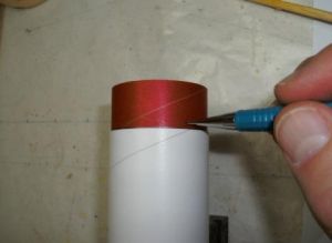
- Couple the stages and using the marking guide from the instruction sheet, mark the body tubes.
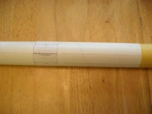
Extend the fin marks across both tubes, and the launch lug line the entire length of the sustainer. Make a mark 1/8" from the stage joint on both stages. This is where you will glue the fins, creating a ¼" gap between fins. - Sand and seal the fins from both kits.
I use three coats of wood glue thinned 50% and sand with progressively lighter sandpaper with each coat, but use whatever method you prefer. I rounded all but the root edges, but a tapered shape would certainly not hurt. - Glue the fins to the rocket.
I glued both stages at the same time in order to get them to line up. I also rotated the booster to make sure they lined up in each direction. - Cut one of the launch lugs in half and glue one piece to the sustainer between the fins and the second at the last body tube/coupler joint. Site through the lugs to make sure they line up.
- When the fins and lugs are dry. Apply fillets to all joints. I constructed a simple cardboard cradle to hold the rocket as I did this.
- Tie both shock cords together and attach them to the sustainer as shown in the instructions. The nosecone and parachute also assemble the same as the instructions. The only modification to the recovery system was to use both cords on one rocket since I find the Estes cords a bit short most of the time.
- For finishing, I applied two coats of Tamiya grey primer, sanding with 400 grit between coats.
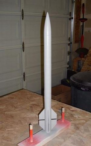
I then finished with two coats of Tamiya Bright Yellow.
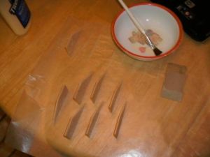
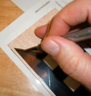
- I used two of the kit decals to make the roll pattern and the ovals between the fins. I then cut the stripes off of one roll pattern for the rectangular blocks on the booster
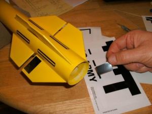
and using the scrap wood from the fin die-cut sheet cut the other stripes into the angled blocks on the sustainer.
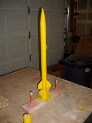
- Photo 26 shows the completed rocket. I really like this kit and have build several incarnations of it. Photo 27 shows the stock kit along with the yellow jacket and a scale Little-John built from the same kit.

Flight:
Using Winroc I found the center of pressure for the sustainer is 18.35" from the tip of the nose, and for both stages is 21.5". I had no problem achieving a balance point well ahead of this location in any test motor combination I tried.
For the first flight I chose to test the sustainer with a B6-4. I applied masking tape to the motor until it was a snug fit, and as an added precaution, I taped it to the motor mount.
The flight was perfect. The ejection was at apogee and was a reasonable height for a rocket of this size.
Encouraged by that flight, I prepped for the first two-stage flight. I taped an Estes C6-0 motor to a Quest A6-4 with cellophane tape. I then added masking tape to both motors until they fit snugly into their respective mounts. With the A6-4 in the sustainer, I added a ring of masking tape around the motor and the motor mount. With that in place, I slipped the booster into place until the engine block was up against the nozzle. I then inserted the igniter and plug and put it on the pad.
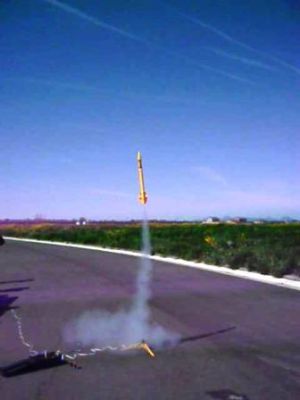
The rocket lit on the first try and climbed out with authority.
There was a slight pendulum rocking back and forth in the climb, with a lazy corkscrew, but it was a very windy day, so some buffeting was not a surprise. Staging was smooth, and the sustainer climbed out very straight. To my relief, the booster tumbled rapidly end over end which did a good job of slowing its fall. (I had been concerned that the reverse-fins would make it fall ballistic, but it worked perfectly.) Ejection was at apogee and the chute deployed without incident. Overall, it was a great flight.
For the third flight I wanted to try the maximum load in the rocket. I taped a C6-0 to a C6-7 with cellophane tape, but could not find my masking tape. Instead I taped the assembly to the sustainer with electrical tape. Everything else went together as planned.
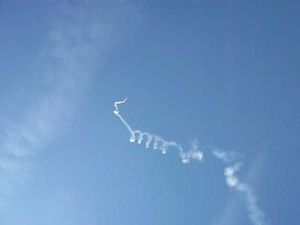
Takeoff was normal, and the same pendulum rocking was experienced in the climb out, but when staging occurred, all hell broke loose. I heard the second stage light, and the smoke trail suddenly started a wild corkscrew...
To my surprise, from the cloud of smoke emerged the second stage, floating gently on its chute. The motor continued to fly wildly on its own, and then I heard the "pop" of the ejection (So it was not in upside-down as some have speculated).
I was able to recover the first and second stages, and to my surprise the booster's motor was intact,
but the sustainer's motor mount was gone leaving only the upper centering ring attached by a flap of paper on one side.
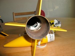
The second surprise was that all the wadding was intact
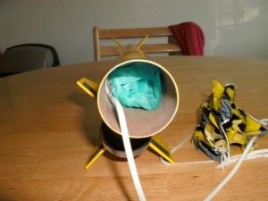
so there had been no ejection, or motor blow-through.
I do not know exactly what went wrong, but I speculate that the two motors failed to separate completely, perhaps getting hung up by the electrical tape, and instead blew out the side. The pressure build up, in the inner-stage area, forced the lower stage off, pulling the upper motor out of the rocket, and taking the motor-mount with it.
The resulting gyrations were enough to dislodge the nosecone, which pulled the chute out when it separated, saving the rocket.
Summary:
The rocket is still in good shape, and I want to install a new motor mount in the sustainer using plywood centering rings. But with that mod, it will no longer fit the contest. I think it is still a viable design, but you might consider some way to strengthen the upper motor-mount if you choose to build it.
#Related Reviews
Related Products
 |
 |
Flights
|
|