| Construction Rating: | starstarstarstarstar_border |
| Flight Rating: | starstarstarstarstar_border |
| Overall Rating: | starstarstarstarstar_border |
| Manufacturer: | Leading Edge Rocketry  |
Brief:
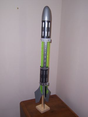
The Alien is a single-staged mid-power rocket with a 20" nylon parachute, metallic wraps and decals, and 39 LEDs, animated by a micro electronics module that allow night launches and recoveries. It is the third and largest rocket so far in the "Night Flight Equipped" line of rockets from Leading Edge Rocketry.
Construction:
There are over 100 individual parts in this kit, so it is more than just a 3FNC. The kit comes with two hardware packs, a centering ring pack, three LED packs, a wiring pack, and loose parts. A complete list of parts is as follows:
- Hardware pack 1:
- Kevlar cording, ~16 in
- Elastic shock cord, ¼ in x ~24 in.
- Screw eye
- E-size engine hook
- 2 Launch lugs, 1 in x ¼ in
- Hardware pack 2:
- 3 AAA battery holders
- 1 Pull switch
- 1 Pull pin with "Remove before launching" tag
- 6 Screws
- 6 Star nuts
- Centering ring pack:
- 1 "A" ring
- 2 "B" rings
- 3 "C" rings
- 1 "D" ring
- 1 spacer
- LED packs:
- 1 White (12 pack)
- 1 Aqua (9 pack)
- 1 Green (18 pack)
- Wiring pack:
- 1 Copper foil roll
- 1 Electronics module
- 2 Red wires
- 2 Black wires
- 2 Gray wires
- 3 Yellow wires
- 3 Green wires
- 5 Blue wires
- 4 Buss wires (bare wire)
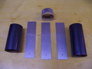
- Loose parts:
- 1 Nose cone, Balsa, pre-weighted
- 3 Main body tubes (BT-80)
- 1 Engine cover tube
- 1 Airframe tube
- 1 Large coupler
- 1 Fin pack (3, basswood)
- 3 LED panels
- 1 LED template
- 1 Nylon parachute (20 in)
- 3 AAA batteries
- 8 Vinyl decal sheets
- 3 Fluorescent acrylic ribs (green)
- 1 Instruction manual
The instruction manual is very detailed and complete, with an abundance of colored illustrations, clearly indicating each instruction step. The instructions are logically ordered and need to be followed as written to assure a successful build because of the complexities of the electrical wiring. I built one of the first kits shipped, and it was missing the Hardware pack #2 and had acrylic ribs that were machined slightly wrong for fitting the centering rings properly. I contacted Leading Edge, and Tim Ziegenbein quickly responded by telephone, explaining that they knew about the machining issue and would send a new set of ribs along with the missing hardware pack. As it only required a little filing to fix the ribs, I did this myself and didn't have the ribs shipped. Tim also pointed out two mistakes in the wiring instructions they had caught after they shipped the first kits. The customer service provided was exceptional (more on this later).
The kit requires you to supply wood glue, CA glue, and 5 or 30 minute epoxy, a small soldering iron and solder, small wire cutters and long nose pliers, scissors, permanent markers (blue, black, and red), and the standard hobby knife, ruler, and masking tape needed by all rockets. To finish the rocket to look like the prototype you will also need chrome and clear spray paint, balsa fillercoat, sanding sealer, a good sandable primer, sandpaper, and masking tape.
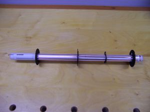
The internal airframe assembly starts by gluing up the centering rings, marking the locations for the centering rings on the airframe tube using the acrylic ribs as guides, and then removing the parts from the marked airframe tube (19.25 in). The engine hook and thrust ring are installed on the airframe tube, and then the fun begins: the adhesive-backed copper foil is applied to the airframe tube in specific locations with regard to the acrylic rib positions. Three different electrical circuits are established and marked as red, blue, or black using the permanent markers. Careful attention to detail is needed here, and careful alignment of the foils will assure an easy assembly later. Once the foil is in place, solder is applied at specific cross-over points to bridge the copper foils and create complete circuits. Use a small iron and do not overheat the copper foil, as this can destroy the adhesive and scorch the cardboard tube. Keep the amount of solder to a minimum and with a flat profile, too. At this point the centering rings are put back on the tube (they need to slip over the solder joints, so no big blobs of solder), the acrylic ribs are dry-assembled to align the centering rings, and the centering rings are glued to the airframe tube using thin CA (do not get the glue on the acrylic ribs). The acrylic ribs are removed to allow the pre-slotted engine hook cover (3.5 in) to be slipped over and glued to the airframe tube. The alignment of the slots in the engine hook cover is such that one set of three slots aligns with the acrylic ribs, and the other set of slots is for the fins that will be attached later. The slots were not well positioned on the engine hook cover tube, and I had to make some slots wider to properly align with the ribs and fins. This was, however, along with the machining issue with the ribs, the only real issue with the fit and finish of the parts: the centering rings, tube lengths, acrylic fin lengths and overall machining, the pre-weighted balsa nosecone, the laser-cut basswood fins, and the LED panels were of the highest quality. The airframe was then completed by attaching the three acrylic ribs to the airframe tube and centering rings using epoxy, adding the Kevlar recovery cord (shock cord mount), and attaching the fore centering ring to the body tube and acrylic ribs with epoxy.
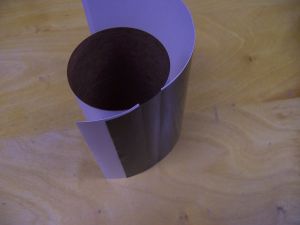 The external airframe was assembled in three distinct sections. The aft section is a short section (1 in) of BT-80 tubing with six equidistant spaced holes for LEDs. The section also has a spacer and a coupler section that are installed to establish a groove on the inside of the BT-80 tube to house the LED wiring harness. The second airframe section is a piece of BT-80 tubing (4.875 in) that couples to the aft section using the coupler segment (do not glue together) to complete the aft section. The third section is the fore section, a 6 in piece of BT-80 tubing with six more equidistant spaced holes for LEDs, which will also house the parachute and nosecone. Before any further assembly, the adhesive-backed vinyl coverings were wrapped around the external airframe tubes. The amount of vinyl was just sufficient to cover the tubes, so careful alignment of the vinyl sheets was required. To wrap the body tubes I trimmed the paper backing (both layers) off the edge of the dark gray vinyl wrap that would correspond to the end of the body tube cylinder. By removing a strip of the backing paper in the middle of the wrap, I could set the body tube upright on a flat table top, wrap the vinyl around the cylinder, aligning the trimmed edge with the cylinder end on the table, and make adjustments to the alignment, as I could reposition the vinyl because so little was in contact with the body tube. Then it was just a matter of removing the rest of the backing paper and carefully smoothing out the bubbles. I used the same technique on the silver accents (a spectacular feature), trimming the end of the decal that circumnavigated the cylinder when applied.
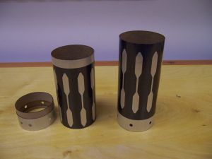
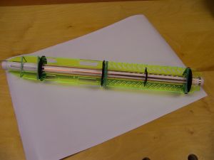
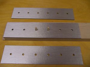 The three LED panels were assembled from the cardboard fiber panels, more copper foil, electrical tape, and six LEDS (green) by carefully following the detailed instructions. Before assembly began the flat panels were covered on one side with silver metallic vinyl. I made a jig to attach the vinyl to the LED covers. The holes in the vinyl were not spaced perfectly to match holes in the covers, but by referencing on the center two holes (see dowels in picture), the error got spread out so there was less than 1/16" misalignment on the outer holes. The LEDs were soldered onto the copper foils to create two circuits per panel, and three wires were soldered to each panel to provide a means of later connecting the LED circuits to the copper traces on the airframe tube. Once assembled, the panels were epoxied onto the airframe, using binder clips and rubber bands to hold them in place until the epoxy set. The color-coded wires were soldered to the matching color copper traces on the airframe assembly. This creates an 8 in long middle section with exposed acrylic ribs and three 6-LED panels. Spectacular look.
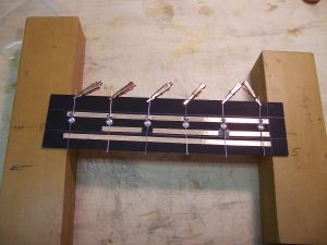
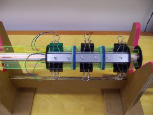
Acrylic rib lighting was established by positioning nine LEDs (aqua) into recesses machined in the ribs, soldering the leads to the airframe traces, and epoxying the LEDs in place. As with all LED installations, careful attention must be paid to orienting the LEDs correctly in the circuits, as they will only work if install correctly. The instructions are very clear on this well-illustrated point. The battery holders are attached to holes in the ribs with screws and star-nuts. Care should be taken not to overtighten the nuts to avoid cracking the acrylic rib. The holders are connected together in series by wire and solder. The two LED rings are soldered together on a template provided to establish the proper spacing. Six LEDs (white) and two lengths of bare wire are used for each assembly, to which two color-coded wires are attached. Care should be taken to minimize the amount of solder used in each connection, avoiding large blobs of solder. The two LED rings were then installed inside the external body tubes by inserting the LEDs through the holes in the tubes and epoxying the LEDs to the inside of the body tubes. I held the LEDs in place using binder clips while the epoxy set up. Ensure that the epoxy does not create blobs that have a high relief, as this will interfere with installation of the body tubes in the next step
 The electronics module was installed by soldering its color-coded wires to the matching color-coded copper traces of the airframe tube, the battery holders, and the pull switch. The outer airframe segments were then slipped over the inner airframe assembly with care, making certain the LED rings clear the centering rings. I had to remove the LED ring on the aft body tube segment, slip the body tube in place, and reinstall the LED ring because my solder joints and epoxy blobs were too large to allow clearance of the aft centering ring. The lead wires to the LED rings were then soldered onto the copper foil traces (this was where Tim's warning about the misprint was so useful, as the instructions in this early version of the manual were in error). Once the electronics circuit has been tested and found working, the pull switch is installed in the hole in the aft external airframe section, and the fore and aft external airframe sections are glued to the centering rings and acrylic ribs using wood glue and epoxy. The middle section is not glued to anything--it acts as the electronics bay cover that can be slid forward to replace batteries. DO NOT GLUE THIS SECTION TO ANYTHING. ALSO, DO NOT APPLY BATTERY POWER DIRECTLY TO THE LEDS. I did this in troubleshooting a poor connection and blew out six diodes in an instant. I contacted Leading Edge Rocketry, explained my error, and Tim Ziegenbein sent a generous repair package that allowed me to completely rebuild the faulty LED panel, metalized vinyl and all. The customer service offered by Tim and his team was superb.
The fins were finally epoxied to the aft end of the rocket, aligned with the slots in the engine hook cover. Epoxy fillets were placed along both sides of each fin along the body tube and where the fin touched the aft centering ring. The screw eye was then glued into the pre-drilled hole of the nosecone. This finished the assembly that could be done before painting.
Finishing:
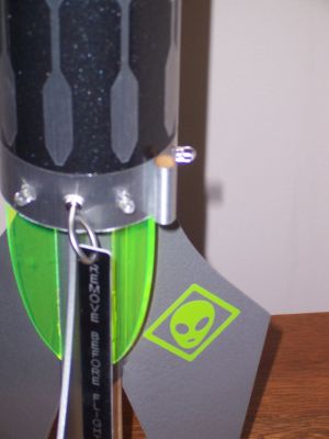
Finishing the rocket started in the middle of the build with wrapping the external body tubes with vinyl, as previously described. The remaining finishing entailed sealing the fins with sanding sealer, sealing the nosecone with first balsa fillercoat, followed by a couple coats of sanding sealer, and sanding with 320 grit sandpaper. I masked off the acrylic ribs and the body tubes and sprayed on one coat of white Kilz primer (enamel based), lightly sanded, and sprayed with Ace Hardware Chrome paint, followed by overcoating with Krylon Clear Gloss. This was the recommended approach and yielded a hammered metallic effect that matched the metalized vinyl foil quite well. I applied the remaining three decals (alien faces) to the fins. The overall look of the finished rocket is stunning, and the light show provided when you pull the pin will surprise you: bright flashing white lights, alternating pulses of green lights, and steady, well lit green acrylic ribs that outline the upper body and tail sections. The instructions did not mention how to attach the launch lugs, but it was apparent they needed to be attached to the fore and aft external body tubes (I used epoxy after wrapping the launch lugs in silver foil from the repair kit I received--waste not this shiny foil!). Overall, this was a complicated build that requires careful detail to clear instructions producing a rocket that will be the star of your mid-power fleet.
Construction Rating: 4 out of 5
 Flight:
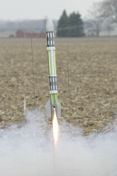
The Alien's maiden flight was on a Aerotech E15-4W (single use) motor in full daylight to test whether the lighting circuitry was going to be rugged enough to maintain the LED flashing that will be required for a night launch in order to track and recover the rocket. Although the boost was stately, the delay seemed abnormally long and the rocket was undergoing ballistic reentry when the chute finally popped. The motor was actually ejected, which surprised me because of the snug-fitting motor retainer. Less surprising was the 3/4 inch zipper resulting from the late delay. The most disturbing thing, though, was finding the nose cone impaled at the tip on the leading edge of the body tube. The shock cord supplied with the kit is too short for the extra weight in the nosecone. Nonetheless, the LEDs were still flashing when I recovered the rocket, and the damage to the nosecone and body tube were not sufficient to prevent a second, angst-filled flight on an Aerotech RMS F12-6T. (I securely taped the engine clip this time to avoid losing the RMS casing!) This was a much better motor and delay choice, as the Alien had another stately launch, continued to accelerate into the gray skies, and popped its chute just at apogee. The LEDs were still flashing upon recovery (circuits look to be very rugged), but the nosecone had a second ding in it (not impaled this time, just a new dent). I will replace the shock cord with a longer version before I fly again, and will repair the damage to nosecone and body tube. This rocket drew a lot of attention at the launch due to its exotic looks, and I look forward to flying at night sometime in the future. The LEDs are very bright and will provide easy tracking in the night sky.
Recovery:
I recommend replacing the shock cord with a longer version and not flying this model on anything less than an E motor as it is just too heavy for a D motor (mine weighed in at 438 grams without the motor).
Flight Rating: 4 out of 5
Summary:
Overall final rating will have to wait until I see how this unique rocket flies and recovers, but I give the construction and finish very high marks, along with the fit and finish of parts, the clarity of the instruction manual, and the superb customer service provided by Leading Edge Rocketry. Thanks Tim.
Overall Rating: 4 out of 5
 |
 |
Flights
|
|
|
|
S.B. (October 19, 2009)