| Construction Rating: | starstarstarstarstar |
| Flight Rating: | starstarstarstarstar_border |
| Overall Rating: | starstarstarstarstar_border |
| Diameter: | 2.04 inches |
| Length: | 13.60 inches |
| Manufacturer: | Estes  |
| Skill Level: | 4 |
| Style: | Scale |
 Brief:
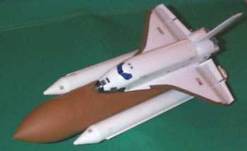
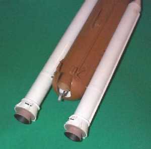
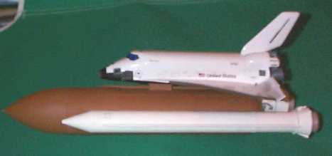
This is a 1/162 scale model of the Space Shuttle in a boost glider configuration. The kit uses a single 18mm engine mount set off-center in the External Tank (ET). At apogee, the Orbiter releases and returns by glide, while the ET/SRB booster assembly recovers by parachute. Auxiliary fin units (removable for display) are provided for stability during flight and are attached into the bottom of each SRB. Estes considers this kit part of it's Master Modeler series and is classified as Skill Level 4.
Construction:
three cardboard body tubes (BT-67, BT-20) plastic nose cones and tail pieces vacuum formed plastic orbiter balsa fins cardstock elevons and centering rings 18mm engine mount incl. metal hook 1/8" launch lugs
 The parts list is extensive for this complex kit which includes a lot of model detail extraneous to flight characteristics.
The instruction manual is 16 pages long and includes 53 construction steps as well as detailed flight trimming and finishing diagrams and instructions. All 53 steps are supported by detailed line drawings. Any potential missteps by the modeler are anticipated and the instructions are subsequently VERY detailed.
The booster assembly and auxiliary fin units are constructed from cardboard tubing, card stock, wooden dowels, and molded plastic parts. There is a lot of care put into details on the ET such as a corrugated wrap, use of a shroud line cord to simulate a vent tube down the side of the ET, a dowel for an oxygen feed line, etc. even though most of the detail is not seen once the Orbiter is placed on the ET for display.
 Assembly of the Orbiter is accomplished using plastic tube cement for some of the joints such as the elevon dowel, but the joints of the vacuum-formed plastic parts need to be done with liquid plastic cement. You brush this adhesive on rather than squeeze out of a tube. It is much stronger than tube cement (watch your sinuses), so you need less to achieve a stronger joint. It is also much less messy, and leaves a better looking joint without distortion. I wish I knew about this stuff as a kid, because all my model ships, cars, and planes would have looked a lot nicer and my canopies wouldn't have been smudged!
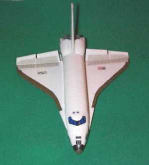
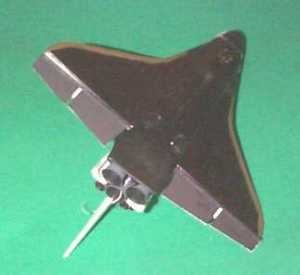
One very important step that the instructions urge is to paint the Orbiter prior to static balancing. This should include most decals and a light coat of clear sealer. This is because the majority of the surface area is behind the balance point, and applying paint evenly over the surface would throw off your meticulously achieved, very fragile, balance. Be patient and gentle when cutting out the holes for the elevon dowels, It is really easy to slip and cut too much in vacuum-formed plastic. The nose of the Orbiter is left to be attached after balancing and flight trimming. Therefore, you have to postpone paint and decals in the small area of that joint, which if you keep to an absolute minimum finishing left to do, should not affect your trim significantly.
 Finishing:
The instructions recommend painting the SRBs white and the ET brown by doing so before you attach them together. If done by spray paint, the instructions point out the need to mask small strips for the adhesive. Since I would then have to go in with a brush to finish painting that joint anyway, I decided to brush paint the whole booster assembly. I used Testors enamel white glossy for the SRBs and rust for the ET. This tended to de-emphasize some of the detail on the ET because of the thickness of brushed enamel paint, and I think I would spray paint if I did it again. A light coat of Krylon white was enough to give a nice glossy finish to the Orbiter, and a good surface for the waterslide decals. Instead of spray paint, I brushed Testor flat black on the underside and used military olive green for the high heat edge tiles. Paint as much of the nose as possible to minimize the effect of finishing on trim after you have attached the nose piece.
Construction Rating: 5 out of 5
Flight:
The two engines recommended are C5-3 and C6-3. I have only used C5-3 to date for that extra little bit of initial peak thrust. The first flight was on a stock Estes 3 foot two-piece 1/8 inch launch rod and some light wind. The rocket went horizontal about 50 feet off the ground and ejected just prior to impact. Fortunately, the only damage was the three Orbiter attachment lugs ripped off. I attribute it to the wind on a large sail area, rod whip, and the auxiliary fins were pushed all the way into the SRBs. The second and third flights have been very straight. I have used a longer 4 foot rod, little or no wind conditions, and the auxiliary fin units are inserted to the aft centering rings just inside the SRB tube with friction fit. Be careful you don't twist the SRB off the ET as you install the fin unit.

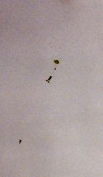
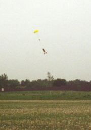
Recovery:
The elevon adjustment system does not work real well, and both flights that went high have ended up with more of a flutter glide with lots of stall due to the adjustment string coming loose and the elevon fail-safe going to full rise. The booster assembly recovers fine on an 18 inch plastic Estes chute or a 12 inch nylon chute.
Flight Rating: 4 out of 5
 Summary:
Overall, this is a very difficult kit to build correctly. The instructions, if followed diligently, will keep you out of trouble. It is an impressive model on display and in flight. Although it is not currently in distribution, it seems like Estes has learned from Disney and will periodically re-release it for the "very last time".
Overall Rating: 4 out of 5
Other Reviews
- Estes Space Shuttle By Dick Stafford
This is a review of the OOP Estes Master's Series Space Shuttle, EST# 1284. It is a 1/162 scale replica of the Space Shuttle and includes both Orbiter and booster sections. These sections are connected at launch, boost on a single C5-3 or C6-3 engine, and separate when the 'main engine' ejects. The Orbiter uses glide recovery while the booster uses a parachute. For flight, there are removable ...
 |
 |
Flights
|
|