| Diameter: | 3.00 inches |
| Manufacturer: | Yank Enterprises |
| Style: | Scale |

Yank Enterprises three inch IRIS featuring Flexible Phenolic
Overview, Assembly Test FlightsBy: Al Casper
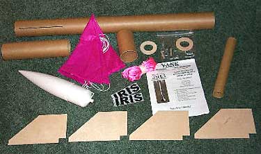 Figure 1: Components of Yank Enterprise's 3" IRIS kit |
I chose the three-inch exact scale IRIS kit for this evaluation. I also put the flexible phenolic through a battery of tests comparing it to cardboard and regular phenolic airframe tubes.
The three-inch IRIS kit (Figure 1) features a pre-slotted flexible phenolic airframe and payload section. Also included: four 1/16 inch plywood fins, tube coupler, plastic nose cone, 1/4 inch centering rings, 38mm motor mount, 9/16 inch tubular nylon 15 foot (non-elastic) shock cord, decals, two quick links and eye bolts, and a quality 30 inch parachute. The detailed instructions are adequately written and the illustrations are well done.
Building The
IRIS
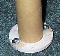 Figure 2: Motor retention mod |
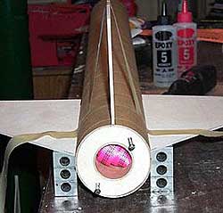 Figure 3: Home-made fin attachment jig |
Step #3. The motor mount is now installed. Here again, I did not epoxy the aft centering ring while installing the 38mm tube. The aft centering ring is in place while the epoxy sets up on the forward centering ring, but will be removed later.
Step #4. In building
the payload section, I smeared the epoxy on the inside of the payload tube, not
on the coupler tube, which would have oozed out and made a
mess.
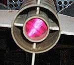 Figure 4: Fin reinforcement |
Step #6. I installed the 1/4 inch launch lugs per the instructions. The Iris, which weighs in at 41 ounces without the motor, is a lot of rocket for 1/4 inch lugs.
Step #7. The recovery
system is installed in this step which was the only one I had any problems
with. I had to re-read the instructions several times before it clicked in.
Once understood, I believe this to be a sound design (Figure 5 6). I
added a small piece of fiberglass cloth and wrapped it around the area
where the shock cords are epoxied together.
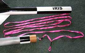 Figure 5: Recovery system reinforcement |
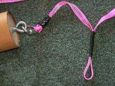 Figure 6: Recovery system reinforcement |
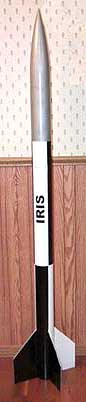 Figure 7: Paint |
Sanding a flexible phenolic airframe is no different than standard phenolic, both of which are much easier to sand than cardboard tubes.
I used inexpensive Wal-Mart primer and paint, following the instructions and provided diagram and was pleased with the results (Figure 7). The decals have a low tack adhesive and require a smooth surface for good adhesion. I sprayed Wal-Mart clear gloss paint over the entire model to give it a nice smooth protective finish over the silver paint, and provide a good base for the decals.
Flexible
Phenolic
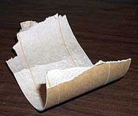 Figure 8: Shredded phenolic tubing |
The flexible phenolic seems to be a combination of cardboard and phenolic. Two thin layers of phenolic form the inside and outside of the tube with a kraft cardboard type of material between (Figure 8). I decided to compare the flexible phenolic with cardboard and standard phenolic tubing.
First I compressed the tubes in a vise -- the flexible phenolic cracked in several places, but held together in one piece while the standard phenolic shattered. Next, I put the flexible in water to see how it would handle a water landing -- after about 30 minutes, it was in almost perfect condition. I performed a zipper test on all three tube types -- the flexible phenolic and cardboard performed about the same, while the standard phenolic suffered the longest cut. In the next test I struck both phenolic tubes with a hammer -- the flexible phenolic again cracked, but held together while the standard phenolic now has a clean gash the same shape as the hammerhead. As a final test, I put the flexible phenolic in a freezer overnight, which did not seem to affect it adversely.
Conclusion
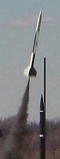 Figure 9: Launch! |
The low thrust motors were chosen mainly to reduce the liftoff-velocity in an effort to obtain some nice photos. The wind scrubbed the G75-J Flight, and the H73-J powered the first flight (Figure 9). The computer simulations called for about an 8-second motor delay, right between a short and medium delay. I chose the medium for two reasons. First, it would stress the Iris, giving it a good durability test during the ejection process. Second, if the Iris heads off into the wind like it should, the longer delay will reduce the walk to recover the rocket.
The IRIS was accelerating as the ejection occurred; the long rigid shock cord appeared to flex in a flat "U" shape, which then softened the jolt as the parachute opened. The result, a perfect deployment, and no sign of any zippering from the rigid shock cord. An H123-W provided the power for the second launch, which was also perfect, except for a longer walk to the landing site.
The IRIS lists at $78.00 retail complete, or $71.00 without a parachute, a welcome choice to have. Yank Enterprises has recently introduced an altitude package for their kits. This package includes a drogue parachute, a second shock cord, and the necessary components and hardware to add dual deployment recovery to your model. Yank Enterprises also offers custom fabrication -- at this time, fins and parachutes can be made to your specifications.
Quality components, workmanship, and a sound design make the Yank Enterprises three-inch Iris a kit worth looking into. Visit their web site at http://www.yankenterprises.com.
Written and submitted by Al
Casper for Rocketry Online -- Copyright 1996-2000


 |
 |