| Construction Rating: | starstarstarstar_borderstar_border |
| Flight Rating: | starstarstarstar_borderstar_border |
| Overall Rating: | starstarstarstar_borderstar_border |
| Published: | 2010-11-13 |
| Manufacturer: | Heavenly Hobbies  |
I purchased the Heavenly Hobbies Backdraft because it sounded really different. The site says "The exciting Heavenly Hobbies’ BACKDRAFT is a dual-engine rocket...". Notice is said dual-engine, not cluster. It then went on to describe the rocket this way: "The BACKDRAFT looks like a 2-stage vehicle, with booster and sustainer sections. The propulsion module (booster) holds the primary 24mm engine. The sustainer holds a secondary 24mm engine. But the BACKDRAFT is not a 2-stage rocket. 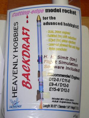 In this model, the secondary engine has exchanged places with the recovery system. The secondary engine has been moved forward, behind the nosecone, while the parachute has moved back. This secondary engine has also been rotated 180°, so that the nozzle points to the sky while the rocket sits at the launch pad. This arrangement sets the stage for the TailWind (tm) delayed deployment system.
"The basic idea for Heavenly Hobbies' exclusive TailWind (tm) delayed deployment system is to reduce drift by skipping ejection at apogee and, after a suitable delay, use a "retro-firing" engine to slow down the rocket for deployment of its recovery system."
Okay, I get it and it surely sounds cool. So, as I said I bought one.
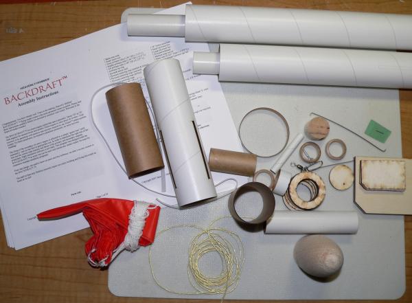
The rocket includes paper body tubes, laser-cut plywood fins and centering rings, 24mm tubes, estes-like motor retention, an 18" nylon parachute, balsa nose cone and piston, and various other standard parts. The parts quality and fit are excellent.
CONSTRUCTION:
The instructions come on a CD and are printed out on 23 pages of 8½ x 11" paper. They contain color photo and illustrations to assist in the build. They also include flying instructions which require you to use the provided H.H. Simit computor software to determine the correct motors.
I would put this kit at a Skill Level 5 for several reasons:
- Instructions can be a bit confusing
- Fairly complex build techniques
- Use of "green fuse" to enable the TailWind motor
When building this rocket, do not attempt to skip ahead and build some sections before others. Follow the instructions.
Many common techniques are used on the build, so I won't comment on those. On the other hand, I will comment and provide some warnings/tips for key areas of the build.
First warning/tip comes when the instructions say to tape (masking) the motor hook to the motor tube. The instructions then said to put glue on the motor tube and slide a plywood centering ring over the hook and up until it stops on the outward bent forward end of the hook. (picture from the instructions below)
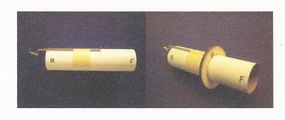
Well, the order of this prevented it from working, because I could not slide the centering ring over the masking tape. So I removed the masking tape, slid the centering ring over the hook and then taped the hook in place below the ring. I then applied glue and slid it into place.
This order of things is repeated for the secondary engine hook as well. However, in this case it caused a greater problem, because one of the last steps is to slide another centering ring down from the top of the rocket (where the nose cone fits) onto the secondary engine hook so that there is room for the nose cone shoulder. That tape was in the way and at this point in the build there was no way to remove it!
The next warning/tip was determined at the installation of the motor mount into the body tube. Here the instructions ask that you install the above pictured motor mount into the tube with only the one centering ring. The instructions warn you to "make sure that the engine mount assembly is aligned coaxially with the airframe tube." This was too much of a concern for me, so I made three tabs from scotch tape (PML style) on lower centering ring (the one not glued in place yet) and slide it in place to ensure the tube was centered. The tape tabs allow you to easily pull the unglued centering ring back out of the tube.
The fins are through-the-wall mounted fins and there were no concerns or issues.
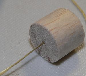
The parachute compartment has a Heavenly Hobbies' EZJect™ balsa ejection piston. This is used to protect and push the parachute out of the compartment. What I found interesting here is that you are supposed to push a flimsy/soft piece of Kevlar through a 1" balsa piston with a little bitty hole!
Well, I did it, but here's the tip... wet the first 2" of Kevlar with epoxy, CA or white glue first and let it dry completely. This will make it stiff and then you can push it through without any issues.
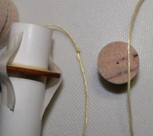
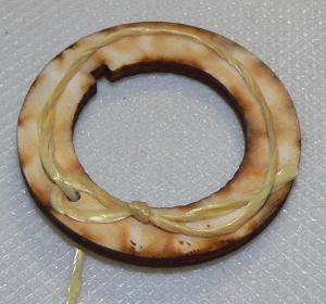 Hey, there cowboy! How's your lasso technique. This was an interesting step in the instructions. The purpose of this is to ensure that the nose cone shock tether is secure around the upper motor mount assembly. Since the shock tether is fed through the side of the upper body tube and the motor mount comes up from the bottom, this step is necessary. The instructions are clear and if done correctly it will look like mine (to the left).
I did run into a problem. I even posted a request on TRF for help (but it doesn't seem like anyone else is building this rocket!). Jose at Heavenly Hobbies responded to an e-mail requesting help.
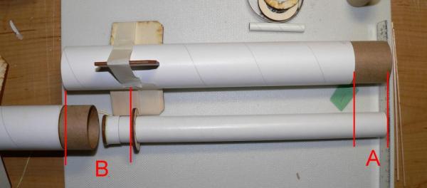
Here's what I wrote: "I'm having some trouble here following the illustrations/instructions associated with steps 6 and 7 on part 12.
"This seems to indicate that we slide the 10.5" long 24mm tube with the cap and EZJect into the middle 10.5" BT50 (one with 3 upper fins). As you can see from my picture, if I follow the instructions, my 10.5" 24mm tube will not be long enough to reach the end of the 3" couple that is sticking out by 1.5".
"Am I reading this correctly or did I mess up somewhere?"
Jose answered back, "Section II.B, on page 10, instructs you to glue the front section (17.25") of the inner body tube to the middle section (10.5"). If you do that, the inner body tube will be long enough to protude past the coupler in the F end of the middle airframe."
Then it hit me and therefore I replied this way: "Okay, I see this. So the confusion comes in back at step 7 on page 8. I read use the coupler as a "plunger" which implied to me to take it back out. The instructions don't say to take it out, but I did. So now, once I put it back in and follow the instructions below, I'm moving again."
 The nose cone is next. It is already hollowed out and has two holes drilled in the sides for use with the "green fuse". The nose cone needs to be protected since it takes the thrust from the TailWind motor. To do this the inside of the nose cone is coated with high-temperature epoxy and the shoulder is protected with a piece of aluminum foil that is glued into place.
When the TailWind motor ignites it will blow off the nose cone. Here is another warning/tip. Be sure to test fit the nose cone with the aluminum foil wrapped, but not glued, around the shoulder. I had to sand mine to ensure a good fit. Once a good fit is established with the foil wrapped around it, then use a very thin layer of glue under the aluminum foil so that it doesn't add any significant diameter to the shoulder.
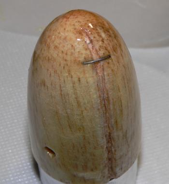
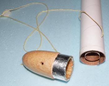 As mentioned, the nose cone will blow off, so there needs to be a tether to keep it attached to the rocket during recovery. This is done by attaching a small piece of piano wire into the outside surface of the nose cone. This spans the groove in the nose cone (see picture above right). I don't know about this, but it is done.
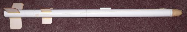
The tether is then run down the length of the body tube and loosely taped to the side of the rocket.
This essentially completes the build of the rocket.
Overall, for CONSTRUCTION I would rate this kit 3 ½ points. Following the build sequence is crucial. I personally got confused with some of the parts/instruction nomenclature so I believe some improvement could be made. The part fit and quality are excellent. There were no decals.
FLIGHT/RECOVERY:
Since the flight may be difficult to visualize, I asked Heavenly Hobbies to make a flight plan diagram. Jose did a nice job as you can see below.

NERRF4 Flight Attempt:
First off, I'll say, I blew it!
I purchased fuse from Heavenly Hobbies and then asked them how fast it burned. They indicated to me that it burned 0.57 inches / second. Therefore, I could have used a 12 second fuse, of 6.8 inches, according to H.H. Simit software, while flying on an Estes E9-4 booster and an Estes D12-3 reverse motor.
If all went as outlined, the flight log would look like the below graph from H.H. Simit. You can see a flight to about 650 feet, then falling to about 300 feet, ignition of the reverse motor which would bring the rocket back to about 450 feet and then ejection and parachute recovery.
Instead, I "remembered" the e-mail saying 0.57 seconds / inch and used a 20" fuse. This created a 35 second fuse!
Now that I admitted my failure, I'll describe my overall experience:
I was successful installing the fuse into the reverse motor and having it held in place with the toothpicks and masking tape. I then taped an Estes ignitor onto the fuse tip with masking tape and stuck an ignitor into the booster's E9-4. Feeling ready (and confident) I went to the RSO table.
They gave me the side-ways look, delayed, asked for 3 opinions, and then finally got NERRF's launch director involved who okayed it.
Out at the pads everything set up nicely, but losing some confidence I angled the rocket away from the crowd just to ensure that there would be no incidents.
The launch time came and the rocket took off nicely. It was stable and went to a nice altitude arced over and started back down. The fuse was smoking so I new it had lit. It came all the way to the ground and PRANG. Interesting, the fuse was still smoking until...
... the D12 lit and the rocket flipped and flopped around on the ground (being substantially crushed) until the motor finished and 3 seconds later the ejection charge fired. So, according to H.H. Simit the rocket hit at a velocity of about 175 feet/second.
The rocket is not repairable and I regret my mistake!
Overall, for FLIGHT/RECOVERY I would rate this kit 3 points. It is clear that I made a mistake, however, I believe for flight and recovery the complex design and requirements make this rocket a challenge. Getting it past the RSO is the first step. Second, if the fuse does not light, then there is no recovery. Challenging.
SUMMARY:
I'm impressed with the kit and I would love to hear about other people's successes.
I think the instructions could use some clarification. I also think the flight and recovery are very challenging and may possibly be too difficult for many rocketeers.
That being said, I applaud the innovation and my experience with this kit has many ideas rolling around in my head for applications of the reverse motor and/or the fuse ignition. I thank Heavenly Hobbies for that.
Overall I would rate this kit 3 ½ points. Even if I had a perfect flight, my rating would be the same. It is a good kit and a unique flight profile, so if you are someone that is looking to try something new... go for it (then tell us about it!).
Other Reviews
- Heavenly Hobbies Backdraft By Dick Stafford (August 2, 2008)
The Backdraft is a BT-60-based, 24mm-powered rocket that on face value looks like a standard 2-stager. If you've read the previous reviews (and I assume you will before you continue past this intro), you'll know that there is one major difference--the upper motor is used as a retro rocket. Heavenly Hobbies calls this the TailWind delayed deployment system. The upper stage is ignited with a ...
- Heavenly Hobbies Backdraft By John Smolley (July 18, 2008)
Presented with written permission from RocketyPlanet: Product Review by Dr. John Smolley, MD Wednesday, June 18, 2008 Photo 1: The many, many parts in this kit are of very good to excellent quality Bungee jumping for the fainthearted? The new Backdraft, a BT-60 based three-foot rocket from Heavenly Hobbies, appears ordinary enough ...
 |
 |
Flights
|
|
J.S. (June 25, 2008)
|
|
C.S. (June 25, 2008)