Mega Daddy 29
By Christopher D. Shramko
2016-01-18
Kit-bash of Estes Big Daddy, Aerotech Initiator packing tube, and Aerotech 29mm Motor Mount. Inspired by the 3D Mega Daddy, my son prepared a RockSim design with separation at the Big Daddy "Fin Can" to Aerotech Initiator shipping tube "Main Body Tube". We've ordered way too many bits and pieces from Apogee, JonRocket, and eRockets. Dry-fit soon. See also Mega Daddy 29.
This is Part I. See also Mega Daddy 29 - Part II.
OpenRocket Proof of Concept
2016-05-19
Our build blog entries are lagging behind our work, which is lagging behind our schedule, but we are catching up!
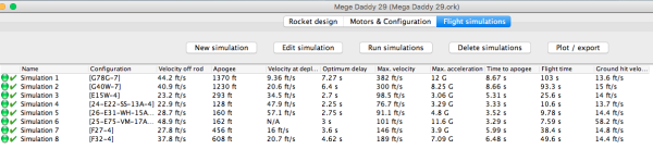
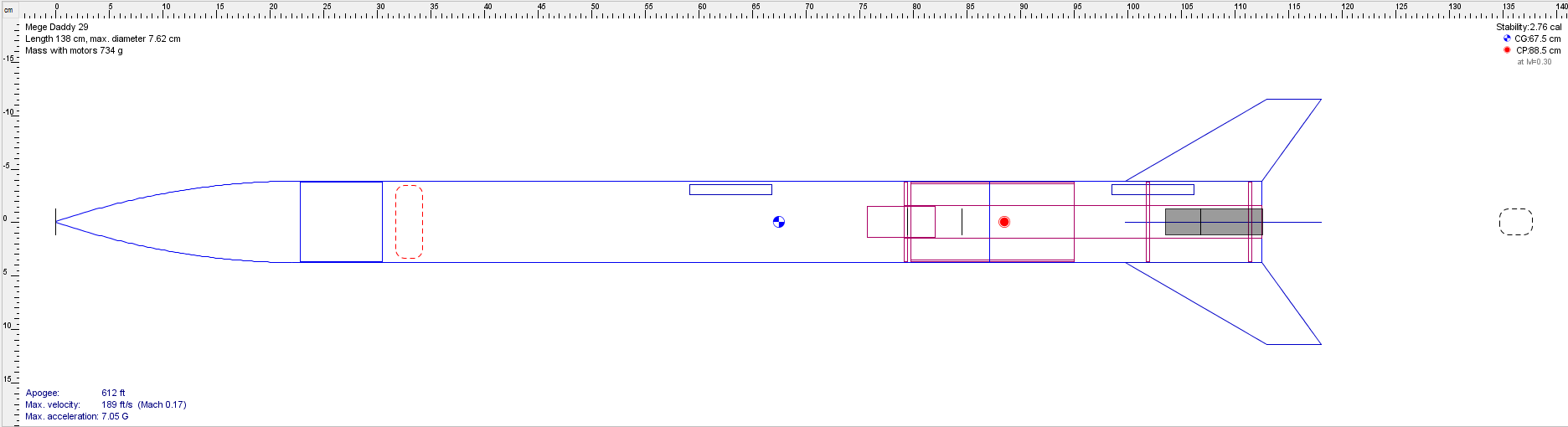
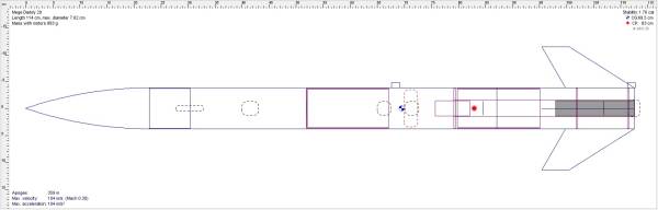
Here is our quick OpenRocket Proof of Concept Study to show that the basic design is feasible.

Bits & Pieces
2016-05-23
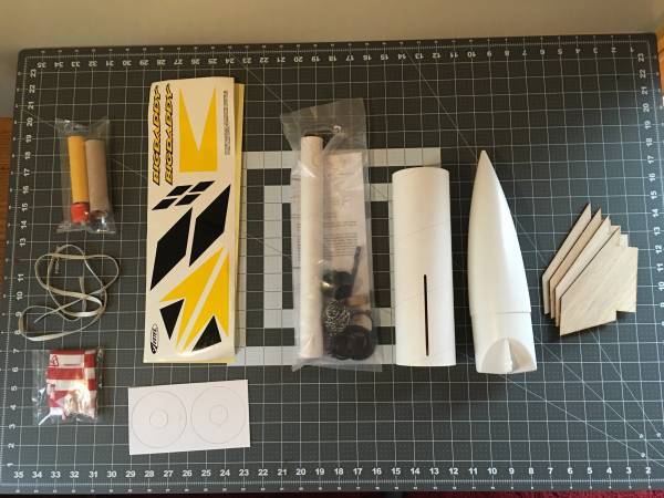
Parts from the Estes Big Daddy kit surrounding the Aerotech Motor Mount kit.
The Estes parts on the left were added to our spare parts bin.
The parts on the right were used for this build (Body tube, nose cone, and fins).

So many options for our launch guide: heavy duty 1/4" launch lugs, surface-mount rail guides, or rail buttons?

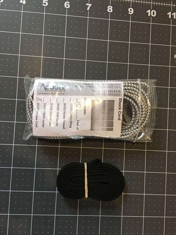
Shock cord: Apogee bungee cord or Aerotech flat shock cord?
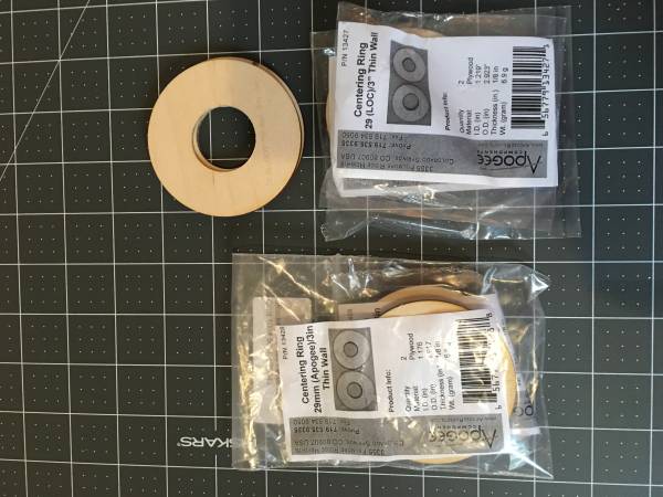
Centering-ring dilemma: Is the motor mount tube considered thick or thin wall?
Is the body tube thick or thin wall, or heavy duty cardboard?
By 3" tube do they mean inner or outer diameter?
There were so many options that we purchased a few hoping for as little sanding-to-fit as possible.
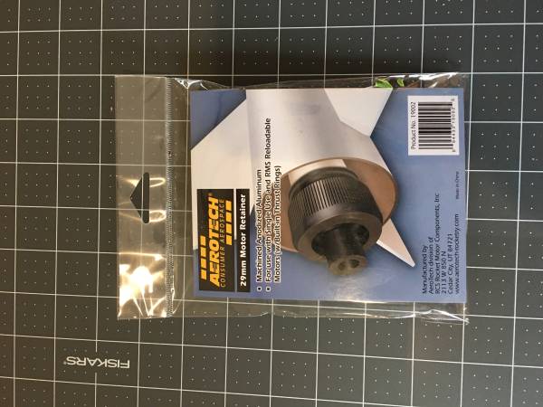
The Aerotech motor mount tube seemed to call for an Aerotech motor retainer.
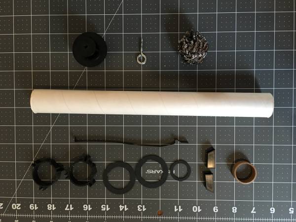
Aerotech 1.9" 3-fin motor mount kit. We used the tube, baffle, screw eye,
and cooling mesh in this build and put the rest in our parts bin.
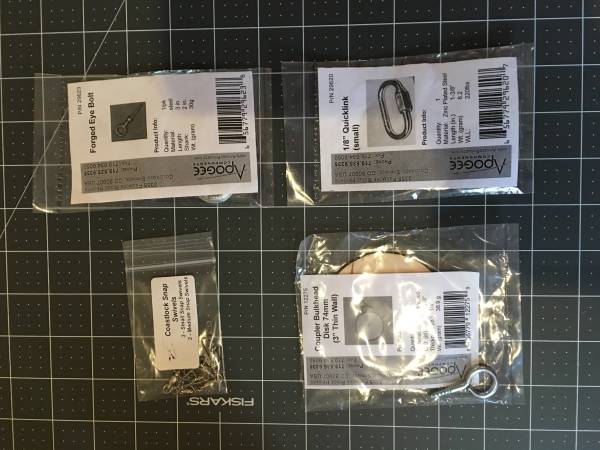
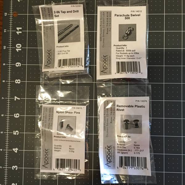
Bulkheads & Hardware.
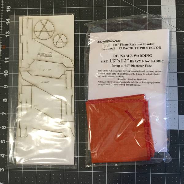
Display stand (which would turn out to be undersized for this build) and chute-protector (it can't hurt,
might help if we can afford a Chute Release, and might be necessary if we drop the cooling mesh and baffle).
Pins & Swivels.
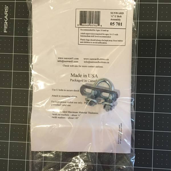
The far-too-big-for-this-application u-bolt.
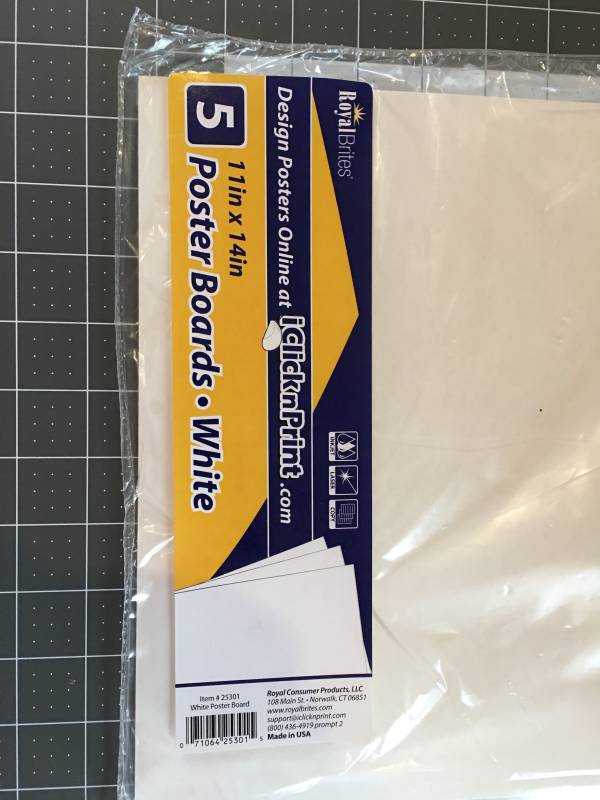
Poster board for skinning the fins.
We are cringing over our failure to rotate all images to the same orientation,
but at least we managed to keep them in focus and avoid fingertips in the corners :)
Dry-Fit of Fin Can and E-Bay
2016-07-11
We dry fit different combinations of parts to find which sized of centering rings, bulkheads, etc., were required, and to see how much material we would need to remove from the through-the-wall fin roots.
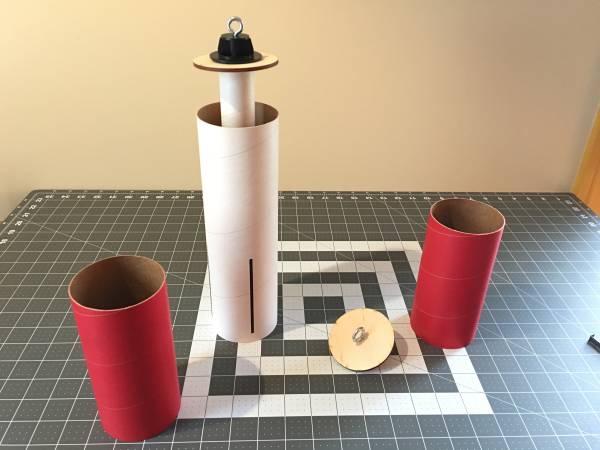

Motor Mount Assembly
2016-07-11
Installation of middle centering ring and cooling mesh to motor mount tube, and top centering ring to tube coupler.

Tube coupler dry-fit on motor mount tube.
Motor mount and tube-coupler dry-fit into fin can.
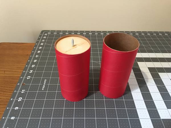
Shortening tube coupler to twice the exposed length to save weight.
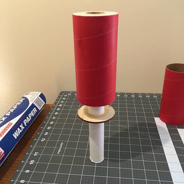
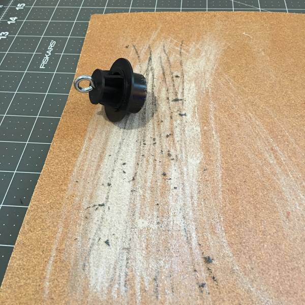
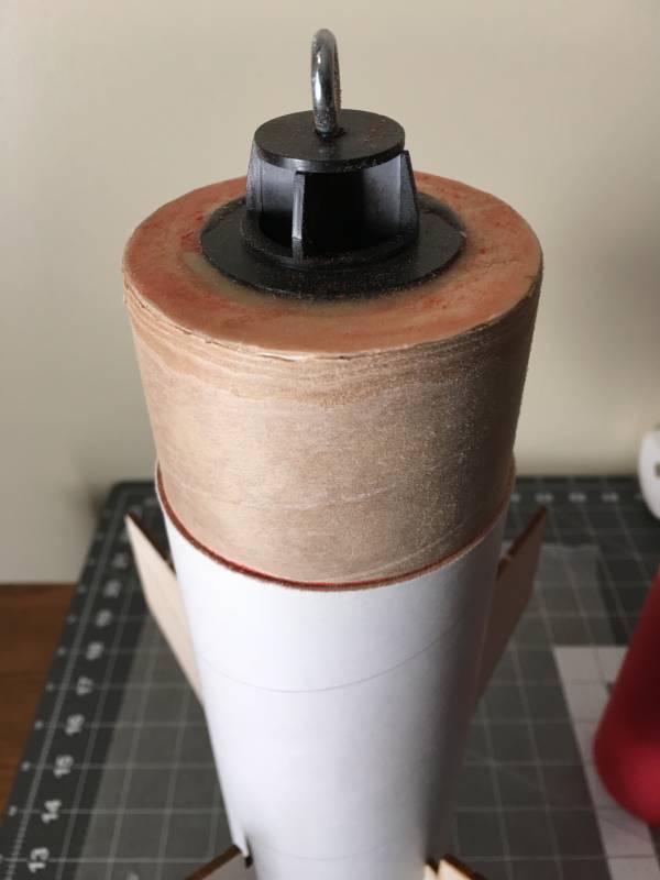
Shock-cord screw-eye installed into motor mount tube baffle, then beveled the bottom edge.
Tube coupler mounted to motor mount tube; removed length of coupler on table for comparison.
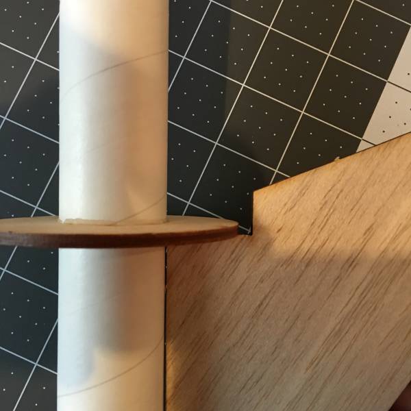
Motor mount installed in fin can, baffle installed in motor mount tube, and top centering-ring coated with epoxy.
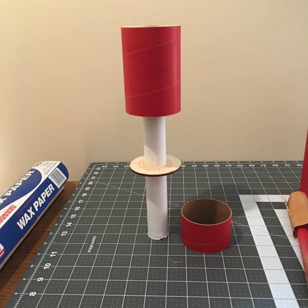
Fin can on display stand, with dry-fit of fins in swept-forward configuration (to reduce fin damage on landings).
Body Tube
2016-07-12
Nathaniel really can't wait to get his L1 certification and to start using electronics bays with dual-deployment. He realizes that he is too young for L1, but would like his rocket to "be ready" for when he is old enough. He is also concerned that we've added too large a volume to the rocket body for engine deployment, and he doesn't like stuffer tubes, so we're putting in an e-bay with only one bulkhead to act as a volume reducer; we can always complete the e-bay build later.
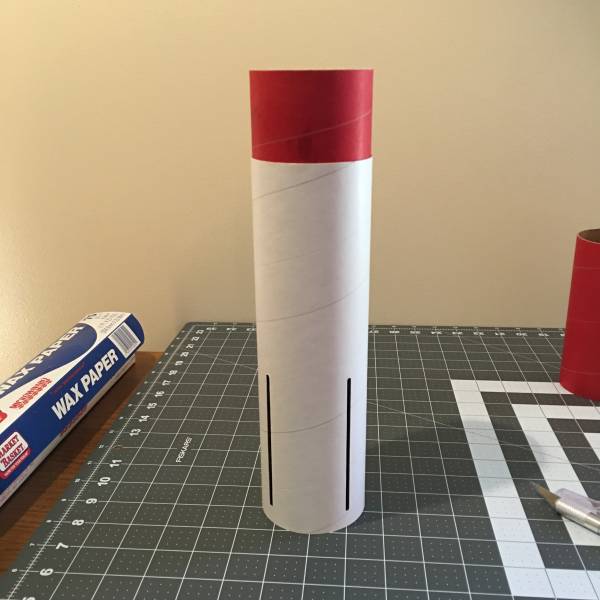
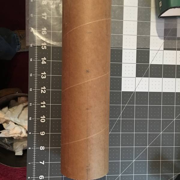
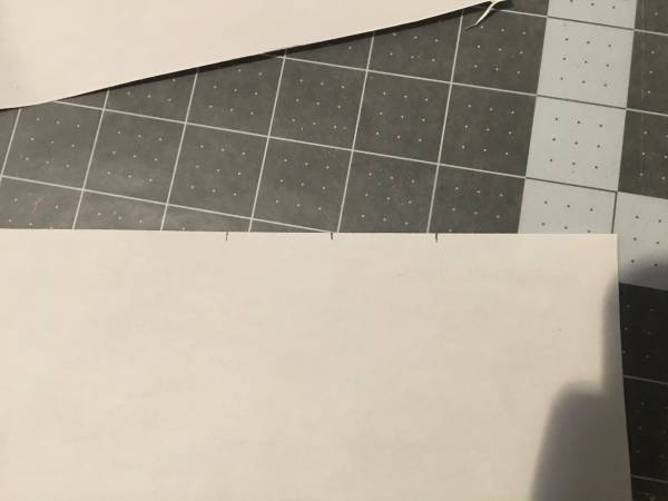
Wrap with marks transferred from two of the fin cut-outs. We then folded in half, aligning the marks, to find the mid-point for the rail buttons, then transferred this mid-point back to the fin can for the "LL" line.

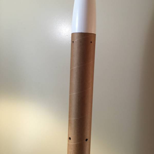
Drawing lines on the body tube for rail guides, e-bay rivets, and nose-cone shear pins.
Dry fit of body tube and nose cone. E-bay with lower bulkhead and shock cord eye alongside.
750 revolutions of 120-grit paper for a proper fit between the fin can and body tube. Next time we sand on the oscillating belt sander before installation.
Shear pins at mid-point of nose-cone shoulder and registration mark.
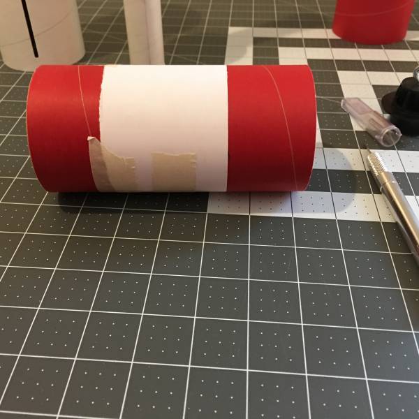
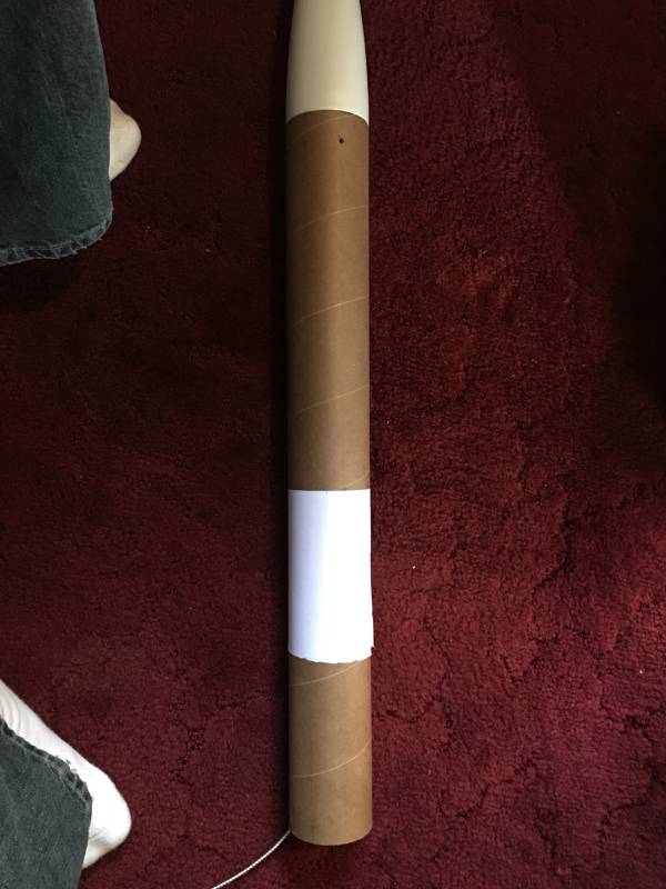
Paper wrap to mark the mid-point of the e-bay on the body tube for locating rivets.
Rivets installed.
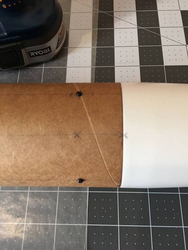
Locating the upper rail button. Top line is bottom of e-bay; bottom line is twice intrusion of fin can. X marks the middle of the two. Why? Because we wanted to avoid interference with either, and our personalities required a calculation 
Open Rocket Design Revision 1
2016-07-12
Electronics Bay
2016-07-12
Our electronics bay will initially have only a lower bulkhead, fixed to the bay tube with epoxy fillets. This bulkhead will have two screw eyes to accept the upper and lower shock cords. We are installing a just-long-enough-to-reach length of shock cord between the e-bay and the nose cone to prevent loss or ballistic re-entry of the nose cone should the shear pins not hold. Epoxy clay was used to cover the screw points to prevent abrasion.

We lost some bristles from the acid brush used to apply the epoxy. We could remove then with tweezers or tooth picks, but we prefer to think of them as "fiber reinforcement". Note that the e-bay tube has already been introduced to the oscillating belt sander.
Shock-cord installed and rivet holes drilled.
Fin Installation
2016-07-12
Paper skinning the fins. Three external edges then coated with thin CYA glue.
Shortening the fin tabs.
Post-shortening dry fit.

Fins installed with epoxy on internal and external fin roots.
Upright drying time. Many builds-in-progress in the background.
After drying, we coated the middle centering ring with epoxy and painted on internal epoxy fillets where the fins meet the body tube, motor mount tube, and centering ring.
We then installed the lower centering ring with J-B Weld, gluing the ring to the fins, motor mount tube, and body tube. The lower rail button insert received coats of J-B Weld under and over, then the whole bottom (centering ring, inside of body tube, and outside of engine mount tube) received a brushed-on coat of J-B Weld and we slid the motor retainer home. As we were excited over our almost-complete construction, we neglected to take pictures 

Paint Scheme Test
2016-07-12
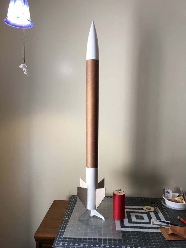
Here's the assembled rocket with a whole can (4 coats) of the neon-est green paint we could find. As we're happy with the results, thick-build primer, sanding, and more coats of neon green will follow.

 |
 |