| Construction Rating: | starstarstar_borderstar_borderstar_border |
| Flight Rating: | starstar_borderstar_borderstar_borderstar_border |
| Overall Rating: | starstarstar_borderstar_borderstar_border |
| Manufacturer: | Quest  |
| Style: | Futuristic/Exotic, Glider |
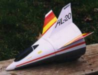 The Quest X-30 Aerospace plane caught my eye, and it was on sale at Magnum for $4. 50, but I was a little wary of the paper shroud construction. Well, the Quest HL-20 uses paper shroud construction, too, and it was also on sale, for $2. 50, and it's supposed to be easier. I figured I'd try the HL-20 as an introduction to paper shroud construction. (I got two of each just in case. )
Construction started out well. It starts by attaching the tri-oval centering disk to the engine tube, gluing a shoulder to the nose cone, gluing the nose cone + shoulder on the tube, and gluing in the engine block. About the only hint here is to use an 18mm engine casing cut around the nose cone positioning disk. It was very thoughtful of Quest to provide an empty 18mm engine casing (intended for use in pushing in the engine block). Nice touch.
Next came the main body shroud. This is made of heavy paper, with the design already printed on it. (No painting, yeah!) I took my time and was very careful when cutting out the shroud, and had no problems with it. The shroud paper comes rolled up in an oval shape in the kit, so it does not immediate roll itself into the desired shape. The instructions suggest laying the shroud printed side down and using a steam iron on it to flatten it out. But, of course, you don't want it flat, so I chose to roll it up close to it's intended shape, and hold it in place with rubber bands while I cut out the rest of the paper pieces. That went fine.
And then came the moment of truth. . . time to put the shroud together, permanently. Provided in the kit for this purpose, is a strip of double-sided adhesive. The idea is to peel back the covering on one side of the adhesive strip, place that on the tab of the shroud, then peel off the covering on the 2nd side, and finally attach the other edge of the shroud. Despite some problems getting the coverings off the adhesive, this actually worked quite well. It took care, but was not particularly difficult to get the shroud edges lined up and held in place. Whew. Whew. It's all downhill from here. . . right?
Nope. The trouble was just beginning. The next step is to attach the engine tube assembly into the body shroud. This is done in two steps. In the first step, you put plastic cement around the inside front edge of the shroud, and push the nose cone (with engine tube and tri-oval centering ring attached) through. The plastic cement is intended to seal the nose cone to paper shroud. The problem is that the nose cone is attached to the engine tube and tri-oval centering ring, and it's basically impossible to get the nose cone to slip through that hole without getting plastic cement all over the nose cone. I wiped this up immediately, but, as you can probably guess, the result was a pretty screwed up nose cone. The plastic cement actually melts the plastic, and anyplace where the cement touched the cone was disfigured. This was almost completely fixed after some sanding with 220 and 400 grit sandpaper, but it wasn't nice. Unfortunately, I haven't been able to think of any simple, clever way to avoid this. Let me know if you figure it out.
The second part of attaching the engine tube assembly to the main body shroud is to apply a fillet of glue around the tri-oval centering ring / shroud joint. No problemo, right? No problemo, right? Wrong. Part of the problem was my choice of glues. I didn't want to be holding this thing all night, so I went with yellow glue (a. k. a. carpenter's wood glue, a. k. a. aliphatic resin glue) because it grabs quickly. Well, it was still a marathon "hold until the glue grabs" session, and not a pretty one at that. The shroud didn't want to form to the tri-oval shape, and it's difficult to hold this awkward shape with even pressure everywhere to avoid waves in the paper shroud. This, combined with the fact that yellow glue shrinks a lot when it dries, resulted in very noticeable waves in the final product. (You can't see them well in the photos, because the white paper gets washed out in the image, but you can see them quite well with the naked eye. )White glue may give better results, but you're going to have to hold it forever. Thick CA, with CA-kicker applied just when things are lined up might be the ideal way to go, but if it leaks through, the end product may end up looking even worse. I've been told that Aleene's Original "Tacky" Glue sets up quick and doesn't shrink so much (and it dries clear); I may try that on my second one.
Well, about this time, I noticed that the adhesive strip that was holding the shroud together, was starting to let go. It wasn't bad, but it was clear that it wasn't going to hold forever. I wicked some thin CA into this area. It's permanent now. It's permanent now. Ok, now this kit is starting to annoy me. . . 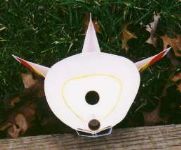
The next step is to attach the fins (I had already cut them out). These are referred to as the rudder (center one) and wings (outer two) in the instructions. These are made of the same pre-printed heavy paper as the shroud. The paper is scored, then folded over once to form the fin. The instructions say to apply a small amount of glue to the inside at the top and pinch together. This forms the proper shape for the fin. This actually worked out quite well, but you have to be aware (and the instructions do not point this out) that the rudder has a wider base than the wings, so you shouldn't pinch it quite as much. The rudder and wings then attached to the main body shroud easily. The main body shroud is pre-printed with the proper location of all externally attached items. Nice.
Next up, attachment of the launch lug and air scoop. The "air scoop" is just a piece of paper attached on the outside bottom of the main body shroud, to form rectangular air passageway. As you can see in the photo above, the launch lug is at the bottom center, hidden between the main body shroud and the air scoop. I thought that hiding the launch lug was a nice aesthetic touch.
Next, adding tail weight. You glue two pennies to a piece of paper, and glue that to the inside bottom of the main body shroud. No problem. 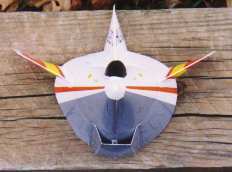
Next, the cockpit canopy. This must be cut from a large piece of excess plastic. It was unclear exactly where to cut, and the instructions aren't helpful here. The idea is that you need to cut so that there's a little base (about 2mm) all the way around the canopy, so that you have something for the glue to hold onto. If you're a stickler for such details, you might want to cut it out with more edge material initially, and try placing it on the shroud to see where you can remove the excess. This piece, unlike the rest of the rocket, requires some finishing, although the instructions don't mention this at all. Having not yet achieved oneness with my paint brush, I opted to use black magic marker. This worked out very well, if I do say so myself. Nice, smooth, glossy finish that didn't take 2 hours to dry. Gluing the canopy in place was simple and straightforward, but it didn't make a complete seal all the way around.
The last step in the instructions makes a small compartment for the streamer (which attaches to the engine for proper recovery when it ejects the engine to enable glide mode). This compartment is a small 1 1/4" long, 13mm diameter (BT-5) tube, with an end cap glued to one end. The streamer is stored here during the boost phase. Well, as accurate as the rest of the paper pieces had been, I was surprised when the streamer compartment end cap was too small. Not a big deal, but odd, because everything else fit well enough. I just used the tube a template and cut a proper end cap from some of the scrap shroud paper. Fixed. Fixed. The instructions just say to glue this compartment on top of the penny ballast holder, inside the back of the rocket. What's missing is whether the end cap should be on the inside (facing forward), or on the outside (facing back). The supplied diagram makes it look like the end cap should be on the outside (facing back). My guess is that that would probably cause the streamer to get caught in this compartment, and thus cause the model to tumble, rather than glide back. I mounted mine with the end cap on the inside (facing forward), as you can see from the rear photo, above.
There is one more construction step (described in the section "Prepping your HL-20 for flight"), setting up the streamer for the engine. Supplied with the kit are a 12" long piece of Kevlar string, and a plastic "gripper" tab. You tie the Kevlar string to the tab, and then attach the tab to the streamer with the adhesive on the tab. Then, for each flight, you tie the other end of the Kevlar string around the end of the engine (reinforce this with tape), and stuff the streamer in the streamer compartment, and you're all set. The packaging says that there's a 24" streamer in the kit. The instructions say that there's a 12" streamer in the kit. Mine measured 11".
The only other step before flight is to hand-toss the glider (without an engine) to get it trimmed properly. In other words, you may need to adjust the tabs on the wings to make it glide in a nice, big spiral. Unfortunately, the model glides like a brick in hand-toss mode, making it basically impossible to trim in any meaningful way. Trimming will have to wait until after the first flight.
To summarize the construction, I have to give this model a construction rating of 2 out of 5. It's not awful or outrageously complex, but there were too many little problems and shortcomings to even give it an "average" rating.
I must preface this flight description and my opinion by saying that it was very windy the day of these flights. It's entirely possible that things would be very different in more rocket-friendly conditions. . .
The launch was held on Saturday, March 14, 1998 at Deer Path Park in central New Jersey. I set up the pad and prepped the rocket. Being a rear-ejection boost glider, there's no need for recovery wadding, but you have to tape the streamer line to the motor itself. The kit documentation recommends a B6-2 for the first flight, but I didn't have any of those, so I opted for a B6-4. There were no problems prepping the rocket, but when I tried to slide it down the launch rod, the engine fell out, and pulled the streamer out with it. No biggie, but I didn't put tape around the engine to get a tighter fit, for fear that the engine would jam at ejection time. I repacked it, and held the engine in place while I set it up this time.
The first launch was ugly. It went up in a wobbly arc, reached about 50feet AGL, and headed down, still under power. I'm not sure if it was still under power when it plowed nose-first into the (fortunately soft) ground, but it definitely hit hard. The nose stuck in the ground, and the ejection charge blew the engine up and out. The streamer separated from the "gripper" tab, making the engine casing, with the Kevlar line still attached, rather difficult to locate. Not exactly a picture-perfect flight, but there was absolutely no damage to any of the pieces, and I was determined to try again.
The streamer was re-attached, and Kevlar line was taped to another B6-4 engine. I thought about trying a C6-3, but was afraid the extra power would simply get used to ram the rocket into the ground even harder. This launch was quite a bit nicer, but by no means a beautiful flight. The rocket went up, a bit straighter, but still hit apogee before burnout. This time, though, it stayed in a nose-up attitude, so the last little bit of thrust had the rocket losing altitude slowly, tail first. Then the engine ejected, and the rocket transitioned to "glide" mode. I'm using the term "glide" rather loosely here, since this glide was pretty much a repeat of my hand-tossed glide attempts. . . more like a brick than a plane. It hit the ground nose-first with moderate velocity, but again, there was absolutely no damage. It does appear to be a fairly sturdy rocket, if nothing else. As for the glide, it simply seems rather nose-heavy, with little in the way of lift. I may try adding more tail weight for the next flight, but, with so little lift, I'm not sure adding weight anywhere is a good idea. Once again, the "gripper" tab didn't grip, and the streamer separated from the engine. All parts were found.
So, the conclusion from the first couple flights was less than inspiring. I will launch this rocket again in calmer weather, and if the flights are much better, I will update this page immediately. I will also try altering the weight distribution to achieve a better glide, and report any successes here. I don't want to misrepresent this rocket, and I'll be the first to admit that the conditions weren't ideal, but so far, I have to say I'm rather disappointed. I have to give it a flight rating of 1. 5 out of 5 points (at least it didn't self-destruct), and an overall rating of 2 out of 5 points. At this point, I simply cannot recommend this rocket.
As a final note, I would like to assure you that I'm not trying to bash Quest as a rocket company. I have several of their rockets, and have been pretty happy with the others. Try the ICARUS or Zenith II, both are very nice rockets that build and fly with quite nicely.
Other Reviews
- Quest HL-20 Lifting Body By Chris Taylor Jr.
Packaging and quality average; not spectacular but not bad either. I would have to say 4 out of 5 though because the Aeroshroud looks really nice and saves a lot of finish work. The package came as a bag with cardboard picture. The aeroshroud, tube, nose cone, and centering rings were inside with the directions. The directions were thorough and easy to follow (well written). The only part in ...
- Quest HL-20 Lifting Body By Alan Rognlie
I had a Centuri MF-24 Bug years ago and the Quest HL-20 reminded me a lot of that kit. This lifting-body boost glider is based on Aeroshroud technology. Translated, that's a printed paper wrapper. ;-) It looks to me like this model was strongly "inspired" by the old Centuri MF-24 Bug - with some "improvements". The only significant(?) differences I see between the two are: ...
- Quest HL-20 Lifting Body By Eric Miller
This rocket was a bargain. My wife got it for me on he clearance rack for $.99. I was disappointed, at first, since the entire rocket is made of painted construction paper except for the nose cone and engine mount. This kit included a paper shroud body, plastic nose cone and cockpit. Fins are paper also. There is a streamer include in kit and it is used to recover the ejecting engine. ...
 |
 |
Flights
|
|