| Manufacturer: | Giant Leap Rocketry  |
Presented with written permission from RocketyPlanet:
|
Introduction
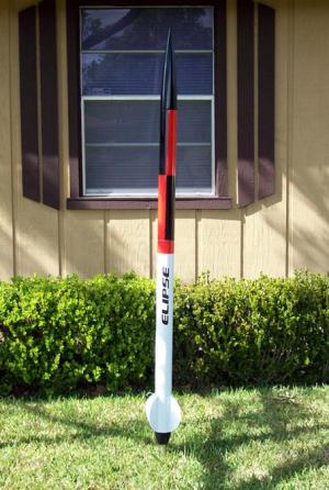
Back at the end of 2006, Giant Leap Rocketry of Baton Rouge, Louisiana, released the latest addition to their family of high power kits named the Elipse. 3" in diameter and 78" long, the Elipse comes with a 38mm motor mount and stands apart from the rest of the crowd with a set of beautiful elliptical fins and a rounded aluminum tailcone.
According to Ed at Giant Leap, "this design was inspired by the lines of the famous Jaguar XKE. I wanted to create a kit with curves that depart from the same old straight lines found in other rockets."
|
But that is just what is visible from the outside - the Elipse has a couple of other innovations hidden inside that can't be seen.
The first is a new fin attaching system called the GROOVE-LOK, an extruded aluminum sleeve that surrounds the motor mount tube and provides precisely-positioned channels to place your fins at the exact, precise point of perfect alignment. It works not only on four finned rockets, but also for your three finned rockets as well, and in two distinctly different thicknesses of fins: 0.062" and 0.093". No need to measure the tube, trying to mark it at the right place. No cobbling fin alignment jigs. Just glue it and go.
The second internal innovation is the HARDPOINT ANCHOR, another use of extruded aluminum that provides a solid forward attachment point for your booster recovery system that is strong, lightweight and still allows you to use motor ejection. This is one tough piece of rocket science. The Giant Leap website states that they dare you to break it, and believe me, if you break this product, you've got far more problems!
Birth of a Project
Giant Leap offered to send me one of the early production Elipse kits to get an objective product review and I jumped at the opportunity. I had just about completed a smaller Giant Leap kit, the Escape Velocity, which was my first Giant Leap kit, but not my first experience with Giant Leap products. In my opinion, Giant Leap has the best rocket components in the hobby and after working with the Escape Velocity kit, the Elipse would be a wonderful point of comparison for me.
|
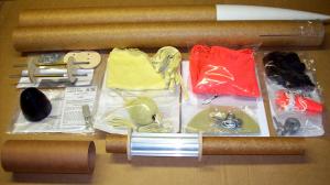
When the package arrived, I immediately dove into it like at kid at Christmas time because, well, it was around Christmas time. For anyone who hasn't yet had the opportunity to purchase a Giant Leap kit, their kits are more than just a rocket kit - it's more like a rocket system. Giant Leap puts just about everything you need in the kit except the epoxy, paint and motors. They truly include more of the necessities than any other kit manufacturer out there, and when it comes down to the small parts like nuts, washers, etc., they really go the extra mile. True to form, the Elipse kit had more included components than anyone can imagine.
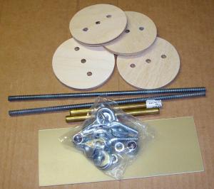
In the pictures, you will see a photo displaying all of the contents of the Elipse kit's packaging. These include:
- 36" 3-inch diameter pre-slotted phenolic airframe tubing (fiberglass version available)
- 24" 3-inch diameter phenolic payload airframe tubing
- 3" phenolic avionics bay, includes coupler, bulkhead plates, electronics sled, and all hardware
- 3" Pinnacle 5-to-1 ogive plastic nosecone
- 38mm motor mount tube
- Two 3/16" birch plywood centering rings
- HARDPOINT anchor extruded aluminum recovery attachment point
- GROOVE-LOK extruded aluminum fin attaching system
- Three .093" G10 curved fiberglass fins
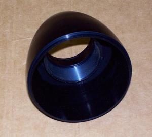
- 3" to 38mm aluminum ogive tail cone with internal Slimline retainer
- KEVLAR FIREBALL recovery zipper prevention device
- Two ACME aluminum rail guides
- Pre-sewn KEVLAR and tubular nylon shockcords
- KEVLAR chute protectors
- 48" main and 18" drogue ripstop nylon parachutes
- ELIPSE decal (not shown in the photo)
As you can see, this is one ultra-complete kit. Standing over six feet tall complete, the dry weight is 4.8 pounds for the phenolic version and 6.5 pounds for the fiberglass version, so this rocket should be well suited for flights on high impulse H, I and J motors. Due to the elegance of this kit, I wouldn't be surprised to see a 4" version with a 54mm motor mount in the future.
Initial Impressions
I started the assembly by reviewing the illustrated 16 page instruction book, making mental notes of things I wanted to pay special attention to, things I might deviate from and generally to see if the instructions were written so that an average flier could follow them without getting lost. I was pleased to see the instructions were clear and easy to follow, and that any time the accompanying photos were of another rocket than the Elipse, it pointed this out to the reader.
After reviewing the instructions, I went through the kit components, dry-fitting them together to get a feel for the assembly steps. This also allows you an opportunity to see if there are any unforeseen problems with the clearances or fit of the various parts as a result of the manufacturing process.
Intrigued with the GROOVE-LOK, that was exactly what I started with. I slid the GROOVE-LOK onto the 38mm motor mount tube along with the centering rings and test-fitted the G10 fins into the fin slots. Giant Leap's cutting on the G10 was very good, with nice square ends where the fins would butt up against the centering rings. I have to imagine cutting smooth curves in G10 is harder than it appears.
As I have come to expect from Giant Leap, their centering rings have the perfect fit and a little pass with a piece of 80 grit sandpaper makes them have just the right amount of snugness on the motor mount. Their airframe tubing end cuts and fin slots are always straight and square. And their phenolic tubing is the best kraft cardboard airframe tubing in the hobby. It has just the right amount of firmness without shattering, just the right thickness and strength and is my choice for any non-composite bodied rocket.
This would be my first Giant Leap phenolic-bodied project that wasn't fiberglassed, so I was interested in seeing how the tubes finished. My primary concern would be to see how the fin fillets worked and how well the spiral groove filled. I was comfortable that the phenolic tubing would have sufficient strength, as Giant Leap's phenolic airframe products have that built in - my mind was on how well the tube would accept the final finish.
Speaking of final finish, traditionally I have used automotive-grade spray equipment to finish my rockets, as I enjoy building and flying rockets, not repairing them. I have found that urethane-hardened automotive acrylic enamels have a much better ability to withstand the normal wear-and-tear of flying rockets. For even the smallest shops, a $200 5HP air compressor and a knock-off automotive spray gun from Harbor Freight is more than sufficient to paint rockets with - the real cost will come in paint, primer, thinners and additives.
For this project, I decided I was going to take a more traditional hobbyist's approach and relegate myself to using spray cans to prep and finish the kit. This would allow me to offer some finishing tips that more people could benefit from that didn't have the luxury or desire to go in the automotive-type direction for finishing. And I think I found some beneficial things from that decision that can help some of the readers who may be using the spray can approach.
|
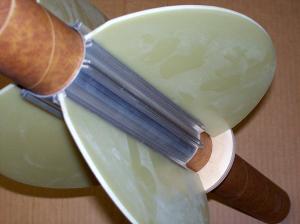
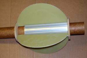
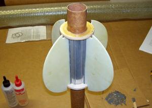
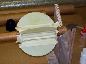
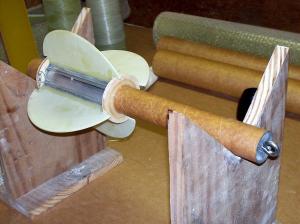
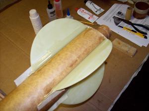
But we've got to assemble this thing before we can paint it, so let's get back to where we left off, the dry-fit test of the components. As you can see from the photos I wanted you to be able to see how the GROOVE-LOK could be used in either a 3 fin or a 4 fin configuration. You might want to mark on the GROOVE-LOK with a black permanent marker which set of grooves you will be using on your projects. That way, when you go to putting the epoxy in the grooves for the fins, you get it in the right grooves. With so many to choose from, that is a small effort to make sure you don't slather up the wrong groove!
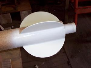
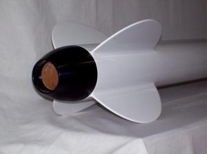
The rounded ogive tail cone is truly a beautiful piece of work. Designed to fit a 38mm motor mount in a 3" diameter airframe tube, black anodized for that perfect look and with a Slimline retainer built in, it's just a piece of art. I loved that finish so much, I decided I wanted to retain the black anodized look, so I decide not to paint the tail cone. As such, I planned to leave the tailcone off until after it was painted, and would need to make adjustments to the instructions so I could accomplish this.
Giant Leap really does a hobbyist good with their avionics bays, including everything you need except the electronics to build your electronics bay. I liked the use of G10 as the electronics sled in the Elipse kit, since my Escape Velocity kit had come with a piece of NOMEX® honeycomb board, which is strong but still has the look of a piece of a cardboard box. Apparently aesthetics and form over function are important to me. And there is plenty of hardware in the avionics bay kit so you don't have to try and run it all down.
|
I want to point out that the avionics bay kit comes with four bulkhead plates: two that will fit inside the coupler and two that will fit inside the airframe. By combining one of each size for use on each end, you form a cap that seats inside the coupler tube snuggly. In my kit, the pre-drilled holes in the bulkhead plates for the allthread attachment rods didn't line up, requiring that I re-drill the holes. Not a problem, really, as I had some other ideas for the avionics bay, and I would end up cutting new coupler end cap bulkhead plates anyway.
Under Construction
I started construction by thinking about the fact that I wanted to leave the tailcone off until after I painted it. That would require me to accurately locate all the centering rings beforehand. In taking the time to consider this, I focused on the GROOVE-LOK and the G10 fins. The fins are about an inch longer than the GROOVE-LOK cylinder, which when following the instructions, shouldn't present any problem whatsoever. But because I can't leave well enough alone, I started considering some small minute changes to the motor mount/fin assembly.
|
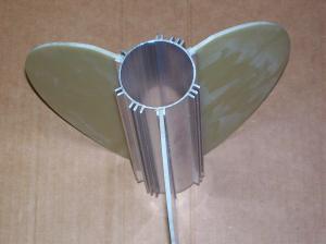
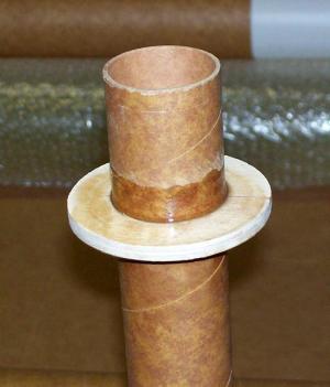
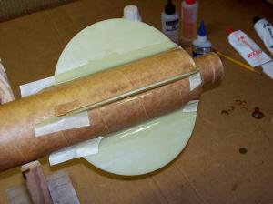
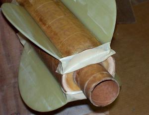
In the end, because I wanted the centering rings to mount flush with the end of the GROOVE-LOk cylinder, and I wanted the fins to be flush with the end of the airframe tubing, I decided to notch the fins on each end to clear the centering rings. You can see the notches in the picture to the left. I notched the front of the fin to clear the forward centering ring and the back of the fin to clear the aft centering ring and allow me to get a 3" hose clamp over the end of the air frame to clamp it down when I glue it up for the final assembly. I wanted to make sure the back of the airframe was snuggly attached so the airframe-to-tailcone fit was precise.
Once these considerations were made and the final position of the aft centering ring was calculated, I marked the 38mm motor mount tube and then sanded the tube with 80 grit sandpaper to give my epoxy plenty of bite. I used regular 12 minute hobby shop 2-part epoxy to attach the centering ring, making a smooth fillet on the aft side of the centering ring-to-motor mount tube joint.
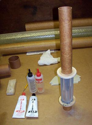
When the epoxy for the centering ring had set, I then sanded the next 6" of motor mount tube with 80 grit sandpaper in preparation to mount the GROOVE-LOK. I also wrapped some 80 grit around a dowel and sanded the inside of the GROOVE-LOK, to roughen up the surface a little. The instructions say you can use regular epoxy, but I like to use J-B Weld on any joint that includes aluminum where heat is involved, and on a motor mount tube, heat is always a consideration. For those who want a slightly larger size than the conventionally small 1.0 ounce tubes of J-B Weld, I found a supplier on eBay what had 5.0 ounce tubes.
|
I got out my J-B Weld and put what I thought was an amount that would cover the necessary area on the motor mount tube, and then carefully mixing the two parts together, I applied it with a craft stick to the motor mount tube. Don't apply it inside the GROOVE-LOK or you will get it all over the motor mount tube and end up with a mess.
Slide the GROOVE-LOK into place over the motor mount tube, twisting it several times to spread the J-B Weld around and evenly apply the epoxy to get a smooth, consistent epoxy joint. After you get it seated, go back to make sure you don't have excess epoxy in the slots that will hold your fins. This is another good reason to mark the appropriate slots on the GROOVE-LOK so you know which ones will need checking for excess epoxy.
When the J-B Weld had set, I applied the upper centering ring with the 12 minute epoxy, and I then added an epoxy fillet to the forward side of the centering ring-to-motor mount tube joint. Afterward, I set the motor mount tube/GROOVE-LOK assembly aside to allow the epoxy and J-B Weld time to fully cure overnight. I didn't want to disturb the J-B Weld before it had fully cured.
|
The next day, it was time to attach my G10 fins to the motor mount tube/GROOVE-LOK assembly. Again, I chose to use J-B Weld at the fin root because of the characteristics of heat transfer when used with aluminum and ordinary hobby shop epoxy. After making sure my fins fit each of their coordinating slots in the GROOVE-LOK, I mixed an appropriate amount of J-B Weld and applied it to the fin root of each fin and slid them into place in the GROOVE-LOK assembly.
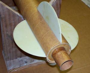
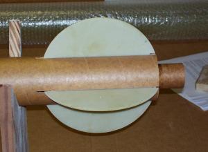
When each fin was seated in the GROOVE-LOK, a slid the motor mount assembly into the rear of the pre-slotted phenolic airframe tubing to use it to help make sure the fins were in perfect alignment. There is no epoxy on the centering rings, only the fin root, because I will take the motor mount tube/fin assembly back out to fillet the fin roots once the J-B Weld has cured.
You can see in the series of photos the amount of distance the fins ended up being moved aft to make them line up flush with the airframe and the size of the notches I cut into the fins to allow me to fit a hose clamp on the aft end of the airframe to clamp it during final assembly. The fin slot openings and the fin notches all get filled during the external fin filleting so this is not a problem.
|
Getting Coupled
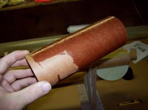
While the fin roots were curing, I decided to coat the coupler tube's external surface with cyanoacrylate (CA) adhesive. I don't know if the coupler tubing is made with a different ratio of phenolic impregnation than the regular airframe tubing or if it simply the difference in thickness, but it just seemed a little less stiff than the airframe tubing. It wasn't flimsy, it just seemed less stiff.
Couplers can take a beating, and I have found out that impregnating them with CA can stiffen them significantly. So, be sure you get a big bottle if you want to do this, and make sure you do it in a well ventilated place. The fumes can be overpowering. I coat the coupler tubing evenly and then once if has fully dried, sand it with 80-120 grit sandpaper to make is perfectly smooth.
Once the J-B Weld had cured on the fin roots, I took the motor mount assembly back out of the airframe and placed it in a level, horizontal position with the fin roots at 45 degree angles to the horizontal and vertical. I mix appropriate amount of 12 minute epoxy and apply this to the fin roots, smoothing the fillets out with a craft stick. You might notice in the accompanying photo that the paper ketchup cups from Wendy's make great epoxy mixing cups.
|
When the epoxy begins to gel, I take 3/4" masking tape and cover the length of the fillet and smooth the tape down. By doing this, I can insure a smooth, uniform fin fillet and I can turn the motor mount assembly 90 degrees and do all four sides of the motor mount assembly one right after the other. By the time I get finished with the last one, the first one is almost ready to have the masking tape removed.
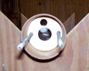
Before I do that though, I attach the HARDPOINT ANCHOR. This extruded aluminum device is assembled by placing the eye-bolt through the anchor, followed by a washer and a nylon-insert locking nut on the other end. Just to be safe, I wick CA adhesive into the threads in case the locking nut ever thinks about backing off.
I sand the outside of the HARDPOINT ANCHOR and the inside of the motor mount tube where it will bond with 80 grit sandpaper. I suppose if I were really anal and I thought the J-B Weld wouldn't hold it, I could have drilled holes through the motor mount tube and into the HARDPOINT anchor for self-tapping sheet metal screws. Even without the screws, the holes would have given the J-B Weld something to ooze into and increase the strength of the bond, but I wasn't that anal and just attached the anchor with J-B Weld. I rotated the anchor as I seated it to evenly distribute the J-B Weld around the joint and then formed a small fillet on the forward end. Believe me, it's not coming out.
|
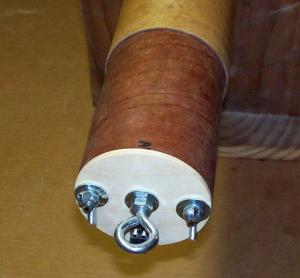
The final motor mount tube/fin assembly is one strong piece of hardware, much stronger than a comparable motor mount/fin assembly of any other manufacturer in the same price range. And to show you that Giant Leap listens to feedback, the original motor mount assembly planned for production in the Elipse wasn't long enough for the AeroTech 38/1080 motor, and when this was pointed out, Giant Leap immediately changed their plans and now includes a motor mount tube that is long enough for that motor in all production kits.
The only consideration a flier might have with the Elipse as designed is that the use of the HARDPOINT ANCHOR would preclude the use of hybrid motors whose length would cause the motor to hit the bottom of the anchor. But that one point hardly overshadows the rest of the excellence built into this kit.
I left the motor mount/fin assembly to cure overnight. The next day, I followed the instructions for attaching the FIREBALL anti-zipper device to the HARDPOINT ANCHOR recovery attachment point. This has to go together as an assembly because the FIREBALL has to be attached at the right distance from the end of the motor mount tube to end up at the correct spot at the top of the airframe tubing.
Final Airframe Assembly
The next step is to mount the motor mount/fin assembly in the airframe tubing for the final time. As unusual as it is when it happens, the additional distance of the fin slots at the forward end of the fins will work out in my favor. Well, sort of.
I fed the FIREBALL into the aft end of the airframe tube, inserting the motor mount part of the way. Using a long stick, I painted epoxy on the inside of the airframe where the forward centering ring would go, and then repeated the process for the rear centering ring. I then slid the motor mount tube/fin assembly into its final resting place and clamped the rear of the airframe tube to the aft centering ring with an automotive 3" stainless steel hose clamp to dry.
While it was drying, I taped up the forward excess fin slots and using the last one, poured in about an ounce of epoxy into the slot. I then taped up this final fin slot and held the airframe vertical while slowly rolling it around slightly off axis to allow the wet epoxy to flow evenly around the top end of the forward centering ring and make a solid bond and internal fillet. I then left it for the night in the vertical position.
The next day, I took off the hose clamp and peeled off the masking tape from the forward fin slots, looking at a solid, one-piece assembly that was light and strong with the fins perfectly aligned. And not a fin jig in sight. It was enough to make a grown man cry.
Instead, though, I positioned the airframe horizontally on my wooden construction supports to apply the external fin fillets. I am extremely demanding that fin fillets be easy to apply but that the result be smooth and uniform. A rocket with clumpy, inconsistent fin fillets is the signature of a poor artist to me.
So I positioned the airframe where the fin roots were at 45 degree angles from the horizontal and vertical, where two opposing fin roots were able to have their fillets applied at the same time. I made masking tape dams at each end of the upper surface and then mixed enough 12 minute epoxy to do two fillets at one time. Did I mention that the paper ketchup cups from Wendy's make great epoxy mixing cups?
You have to work quickly if using 12 minute epoxy. I prefer 15 minute epoxy, but my hobby shop doesn't carry it. The 12 minute epoxy can gel very quickly, so you have to work this quickly. Using a craft stick, pour and spread out the epoxy from one end of the fillet to the other and then smooth the fillet with the curved end of the stick to form the fillet. Transfer epoxy to the other side if needed.
Right when it begins to thicken, take a finger dipped in acetone and smooth the fillet from end to end, taking care to get the centers as perfectly as you can and less about the ends. You should be smoothing the fillet about 3/4" beyond the end of the actual fin edge and wrapping it around the fin edge into the masking tape dam. Use enough acetone on your finger to keep the gelling epoxy wet and use the liquid as lubrication to shape the fillet.
Some people may be sensitive to solvents, so you may want to use a latex glove for this, but I prefer to do it without one so I can judge by feel how far along the epoxy is from setting up. This technique, done right, will produce fillets that need virtually zero sanding except to smooth in the transition between the fin and airframe at the top and bottom. You can see from the accompanying photographs that my fillets are smooth, spartan, with very little excess epoxy or acetone-thinned residue left over. The desired result is less work not more, so paying attention to details goes a long way here.
Because of how quickly the fillets set, you can do all four sets of fillets in less than an hour. I allowed them to set up over night, pulled off the masking tape dams, and then used a rat-tailed file to shape the front edges, transitioning the fillet smoothly into the airframe. The aft edges should remain sharp and square. Combined with some 80 grit sandpaper, the fillets were ready for primer with little work at all. Note: when masking a 38mm motor mount tube for priming, an old toilet paper tube is the perfect size! Cut, slip on and prime!
Electronics Bay Assembly
Once the airframe was completed, with the exception of priming and painting (and of course, attaching the tailcone), I turned my attention to the electronics bay. I had already discovered that the bulkhead plate end caps had very slightly mismatched holes for the allthread that passed through each end of the electronics bay and held it together, but I was planning on altering my electronics bay anyway.
|
For starters, the standard hole pattern that Giant Leap put in the bulkhead end caps would have placed the brass tubes that mounted to the G10 plate and the allthread too close together to allow me to use the four corner mounting method on my ARTS flight computer. I wanted the ARTS to be on the side of the electronics sled with the mounting tubes so that the 9V battery holder could be mounted on the open, unobstructed backside of the G10 plate. That way I could get a wire tie strap under and around the battery holder to secure the battery in place. This would be more difficult to do if the battery holder was mounted on the other side between the electronics sled mounting tubes.
So I decided to make new bulkhead end plates, four in total: two sized to fit the inside of the airframe tube and two sized to fit inside of the coupler tube. When one of each size is epoxied together, they form a solid, stepped end cap that totally encloses the electronics bay. My design adds one additional plywood bulkhead plate as the forward mounting point, epoxied into the payload tube, making the electronics bay completely removable, retained securely by the allthreads, but requiring no screws through the airframe to secure it in place.
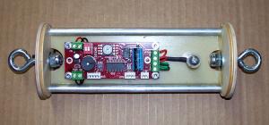
In the accompanying photographs, you can see the assembled electronics bay, sans the coupler tube for ease of explanation. I replaced the supplied brass electronics sled attachment tubes supplied with the kit with longer ones made of aluminum. The electronics sled is permanently attached to the forward end cap only for rigidity, but could have been left separate just as easily. The aft end cap is removable to allow for assembly.
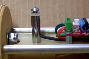
The ARTS is attached via four #4 by 1/2" aluminum electronics standoffs and #4 socket head screws purchased off eBay. The power switch is one of the screw-based power switches from Newton's 3rd Rocketry, epoxied in a 3/8" tube that is screwed to the G10 board. The switch is mounted so that it lines up with the barometric vent hole in the payload airframe for easy arming.
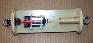
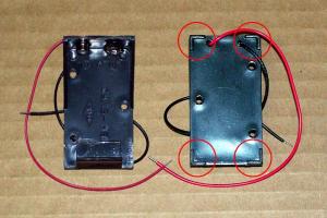
On the back side, the 9v battery holder is also from Newton's 3rd Rocketry, secured with stainless steel flathead screws. Above that is an electronics terminal block epoxied to the G10 board, followed by a section of 1/2" cardboard launch lug configured to be used as a main chute ejection charge holder. A similar electronics terminal block is epoxied to the aft end cap connected with a Dean's connector, for connection of the drogue chute ejection charge.
Assembly is easy and straight-forward: install a new battery in the battery holder, wire the main chute ejection charge. Slide the coupler tube in place, attach the aft end cap. Attach the main chute recovery harness, slide electronics bay over the allthreads and secure it with the two supplied wing nuts. Attach the drogue recovery harness and put the payload section in the airframe, after attaching the drogue chute ejection charge. Proceed to pad, arm the power switch and launch.
I was very satisfied with the products I got from Newton's 3rd Rocketry. The 9v battery holder met my requirements of being strong, light, yet had risers under the mounting pads to allow room for a wire tie strap to fit underneath for battery retention. The power switch is a simple design which combines a nylon bushing as the housing, a brass threaded insert as the switch housing and a screw which contacts the other attachment wire, completing the circuit. I was able to mount it in a very straight forward fashion where I could arm it from the outside relatively easily.
Final Finish
With the completion of the electronics bay, it was time to prepare the rocket for final finishing. As I mentioned earlier, this is the first rocket I had built with Giant Leap phenolic airframe tubing that I had not fiberglassed, so I was interested to see how the spiral grooves would work out.
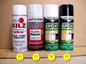
To begin with, I sanded the airframe with 80 grit sandpaper. This process quickly smoothed the airframe and knocked the gloss off. For primer, I used KILZ-brand white spray primer. It goes on heavy, fills lots of imperfections, and sands like a dream. KILZ primer will cover a multitude of sins.
Let me say a word about sandpaper. Do yourself a favor and get good sandpaper. I bought some cheap sandpaper from a local dollar store. This really is a waste of money, no matter how cheap. The grit stays sharp for about 2.5 seconds, or first use, which ever comes first. It still looks like it's all there and it feels gritty, but it just doesn't cut. I then bought some self-adhesive mid-grade sandpaper from Home Depot that was designed to be used on orbital sanders. I bought some that was round, some that was square. They both worked wonderfully, cut well, and lasted a long time. And the adhesive backing makes it a breeze: just fold the sheet in half and sand forever. If you want.
Everyone also seems to have an opinion about wet sanding vs. dry sanding. For most finishes, especially spray can finishes, as well as for most substances like cardboard, you are best to stay with dry sanding. If you are working on plastic or fiberglass, wet sanding is alright because it doesn't invade the underlying material. Water and cardboard don't mix very well, and plain kraft cardboard tolerates water even worse. Not to mention that it is possible with some enamels that water sanding can produce a surface that is TOO smooth for the paint to bite into and will peel in the end.
Speaking of plastic and peeling paint, that also brings up the topic of nosecones. One of the places that most people struggle with is getting paint to stick to plastic nose cones. Fortunately for us, the automotive industry has made great strides in this area, developing primers and sealers that allow paint to stick to plastics very well. At my local Walmart, I found a Rustoleum-brand automotive plastic primer that was designed to promote paint adhesion over plastics like these nose cones are made with. I decided to give it a try.
Giant Leap's 3" Pinnacle 5-to-1 ogive nosecone is a piece of art. It is built with a good shoulder length, a strong recovery attachment area and two different methods of recovery attachment. This is a sturdy nosecone that is much tougher than most.
|
Nose cone prep was straight forward: clean up the parting line seams with a razor blade, light scuffing with 180 grit sandpaper and then a bath using a dish washing detergent like Dawn. Right before priming, wipe with a clean rag dipped in clean acetone. One or two light coats of the primer and then followed up with a couple coats of KILZ primer, the nose cone was ready for the parting line seams to be filled.
For this job, and for filling the spiral lines in the airframe tubes, I chose a standard run-of-the-mill automotive grade spot putty from the automotive department at the local Walmart. You will find it located on the same shelf as the Rustoleum plastic parts primer. Red oxide in color, it dries fast and produces nasty red dust that your wife will hate. Because it's lacquer based, it will shrink as it dries, so you need to allow plenty of time for it to completely dry. As long as a week to be sure.
Fortunately, the spiral lines in the Giant Leap phenolic are small enough that two coats of KILZ primer and one application of the automotive spot putty are all that you will need. Once you have sanded the airframe and nosecone smooth, it'll take a couple more coats of KILZ to completely hide the spiral lines. Different fillers with different consistencies fool you into thinking the spirals are gone, but the only way to be sure is sand it some more and prime it again.
Now, as someone who prefers automotive paint products over spray bombs, I recall all too well the times that I have had to repair spray can paint jobs and the difficulty in doing so, so I wanted to try a spray can paint that was more durable. I had seen some spray paint that said it was epoxy paint, and logic seemed to follow that epoxy paint should be stronger than, well, Krylon. So I decided to try it.
I purchased both white and black Rustoleum-brand appliance epoxy paint, as the Elipse was going to get a sporty two-toned paint job. Let me summarize (and get past my grief) that this product isn't something I would recommend. It doesn't cover very well without being subject to clouding, orange peeling, and on recoats as soon as 30 minutes apart, wanting to lift! I was able to paint the entire rocket with it satisfactorily with the exception of the nose cone, which took three attempts. My recommendation is to stick with Krylon. Krylon works and works well, and you can even water-sand Krylon and polish it out using rubbing and polishing compounds.
The problems I experienced with the appliance epoxy paint seemed contained to the black color that I put on the nosecone and payload section, but since I was going to be covering the payload section with red monokote in a roll pattern, it really didn't matter. It just meant I had to polish the payload section smooth with rubbing compound before I put the monokote on it. While the epoxy paint turned out excellent, I still can't recommend it because it took too much effort for the desired result.
For those wishing to create roll patterns and other striping effects, I can't say enough about self-adhesive monokote. You can cut this to shape, peel off the backing and the apply it to the airframe using Windex to wet out the backing. Now I know it may sound slightly ridiculous to peel the backing off a self-adhesive product and then coat it down with wet Windex. But let me tell you, the procedure works and allows you to apply self-adhesive products without the first air bubble getting trapped under it. Plus the wet backing allows you wiggle room to move the monokote into the exact position you want. From there, you just smooth it out very slowly with a soft cloth to absorb the excess fluid that you work out toward the edges. The rest of the Windex evaporates, leaving a bubble-free surface.
After painting and application of the monokote roll pattern, I installed the tailcone using J-B Weld, then added the ACME aluminum rail guides. All that was left was the "Elipse" decal, attaching the recovery harnesses and heading off to a launch site. All in all, I am very pleased with the way the Elipse turned out. It's a better bargain than most comparable kits price-wise, is constructed with excellent components and certain to last a long time. As pleased as I am with the phenolic version, I can only imagine how great the fiberglass version is. I guess there is only one way to find out!
Flight
The rocket RIPPED on a CTI J335 Red Lightning, heading way the heck into the sky a couple of weeks ago at the NEFAR launch in Bunnell, FL. My ARTS data went haywire when it landed, so I didn't get a good altitude. But it sure looked good going up, on that pretty red flame. It's a great rocket, and one that will get more of my abuse.
Other Reviews
- Giant Leap Rocketry Elipse By William Beggs (October 20, 2007)
Brief: This is Giant Leap Rocketry's entry into the “sport kit” class of rockets. It's touted as the most advanced kit in rocketry. The Elipse is a 3” diameter rocket that stands 78” tall and is not a design you are use to seeing at a regular club launch. Its fins are half circles and with the ogive tail cone it has a very sleek look. The kit comes with just ...

 |
 |
Flights
|
|