Giant Leap Rocketry Escape Velocity 2.6
Giant Leap Rocketry - Escape Velocity 2.6
Contributed by Darrell Mobley
| Manufacturer: | Giant Leap Rocketry  |

Presented with written permission from RocketyPlanet:
Product Review by Darrell D. Mobley
Sunday, July 06, 2008
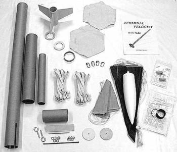
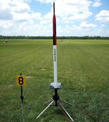
One of the first rockets I got my hands on when I got back into rocketry a couple of years ago was the Giant Leap Rocketry Escape Velocity 2.6, one of their line of "Ready to Fly (Almost)" kits, a 2.56" speedster that includes everything you need other than a motor and launch pad to build and launch your own high powered rocket.
The kit features Giant Leap's signature phenolic tubing, pre-slotted to accept a pre-molded ACME 3-finned fin cannister, a 38mm motor mount, avionics bay for dual deployment, positive motor retention and all the hardware and recovery components a rocketeer could ask for in an all-in-one kit. It looked like the perfect kit for someone wanting to build a rocket that could be used for a certification flight and then flown again and again in a variety of flight configurations.
|
I used the kit in another product review in late 2006, a review about using fiberglass cloth sleeving to laminate and strengthen ordinary cardboard tubes. I got tired early on in my hobby career of the constant maintenance and repair to cardboard-tubed rockets, and even moving up to phenolic tubing came with its own share of troubles like shattered or cracked body tubes. Giant Leap's tubing seems less prone to that behavior than other phenolic kits on the market, but it still weighed on my mind. What to do? The answer was as clear now as it was when I first found the appropriate answer: 'glass it!
As you will find in the Aerosleeves review, I covered the Escape Velocity with one layer of their light fiberglass cloth sleeving, and the strength increase was out of the world. Even though Aerosleeves has gone out of business, you can still find fiberglass and other composite sleeving from online sources such as Soller Composites.
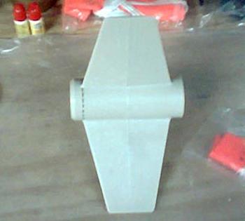
With the airframe handled along with the now non-existent spiral seams, I turned my attention to the motor mount and airframe assembly. It was so straightforward it's hard to believe. With the injection molded ACME fin can, the fins are already aligned at the proper angle, you just attach it to the enclosed 38mm motor mount tube as per the instructions and put on the centering rings. Done!
|
However, I did something a little unique with my motor mount assembly, as I never can leave well enough alone. The ACME fin cans protrude beyond the fins on each end, and when used in conjunction with the Slimline retainer that comes in the kit, tends to make the rocket stick out its behind a little bit. I wanted to tuck its butt back in, so here's how I did it.
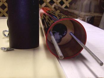
In the photo sequence to the left, you can see the fin can with a dotted line on the end with the taper. I used a hacksaw to cut this length off, giving both ends a flush fit for the centering rings. Then, before getting out any glue, I dry fit the pieces together to see how much room on the motor mount tube the Slimline wanted.
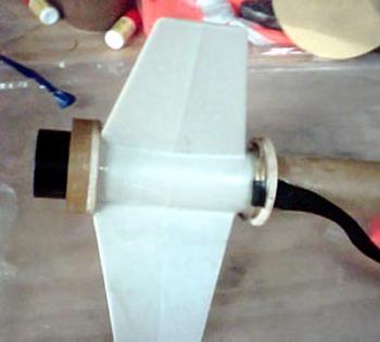
From that, I could determine where the aft centering ring should go, because I wanted the Slimline up against the rear centering ring and the rear centering ring up against the fin can, to recess the Slimline as much as possible while keeping the fin can as far aft as possible.
A short section of coupler tubing designated to join the airframe back together at the rear of the rocket ended up on the outside of the rear centering ring, allowing me to pull things in even tighter. The result was super and speaks for itself. I decided to leave the Slimline off until after painting.
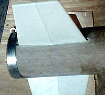
In the last photo of the fin can sequence me, you can see me attaching the airframe and using a hose clamp to snug it on down until the epoxy set.
Another trick I used while assembling the motor mount was the attachment of the tubular nylon recovery cord. The tubular nylon had some nice ends sewn into it, and I couldn't break down and cut them off one end, so I did something one better.
I cut a slot in the forward centering ring for the tubular nylon to pass between it and the motor mount tube. Then, I took a 2" key ring, put it on the end of the tubular nylon, and slid the key ring over the front of the motor mount tube, then fed the other end of the tubular nylon through the forward centering ring and slid it over the motor mount tube. The key ring fit around the front end of the fin can, and I then glued the forward centering ring into place - that puppy isn't going anywhere. You can see the attachment in the second photo of the fin can photo sequence.
The rest of the airframe assembly went as displayed in the instructions. Giant Leap provides great instructions and anyone can follow along with ease, although you should read through them a couple of times to familiarize yourself with all the steps and components.
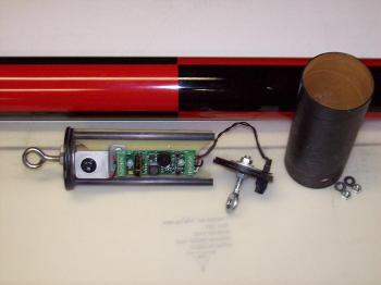
Another area that I deviated from stock was in the electronics bay, which is nothing abnormal for me. The Giant Leap kit contains all of the parts you need for setting up dual deployment in the standard kit, but I am too fat-fingered to want to fiddle around inside a fixed 2.5" electronics bay.
So I created one of my standard electronics bay assemblies that I have covered in an article on building removable electronics bays and in the Elipse review as well. All I needed were some extra bulkhead plates, some T-nuts and a little G-10 for an electronics sled. I should note, the standard kit came with a small sheet of honeycomb material for the electronics sled, but I just love G-10.
|
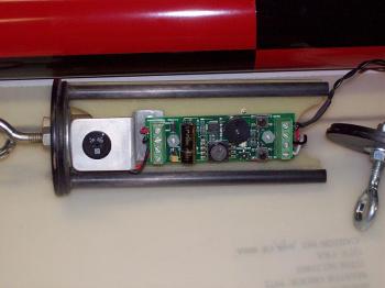
In my designs, I like not having external switches on the airframe that create wiring harness frivolities when moving electronics in and out. By mounting switches on the electronics sled, I can reach through the altimeter port with a screwdriver and arm the electronics very easily.
The necessity of the electronic's switches being in the same place every time so I can find the switch doesn't lend itself to using a single piece of all-thread through the center of the standard electronics bay designs, which allows the electronics sled to rotate around the central axis. By using two pieces of all-thread, I can lock down the positioning of the electronics sled and know my unit is in the same place every flight.
As I have discussed in the previous builds, I use a securely mounted forward bulkhead in the payload section that has two T-nuts for attaching the electronics bay to it, as well as a center cut-out to allow the recovery cord to pass through and attach to the electronics bay, as well as a cut-out to clear the electronics bay's built-in main ejection charge.
The photo sequence to the right shows all of the parts of the removable electronics bay: the sled itself, the end cap, the removable coupler, and lastly the bulkhead mounted in the payload compartment with the two all-thread rods to attach it all together. The electronics sled has a Missile Works RRC2-Mini on the front side along with the power switch mounted in an aluminum bracket.
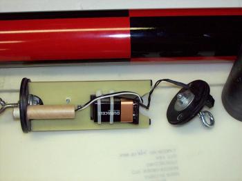
On the back, a 9 volt battery holder resides along with a 1/2" launch lug fashioned to hold the main ejection charge. The electronics bay's end cap has a two-screw electronics terminal for wiring up the drogue charge and is connected to the altimeter by a pass-through wiring harness with a Dean's plug to allow it to be removed and replaced.
To prep, I put in a fresh 9 volt battery and secure it with nylon zip-ties. Next, I fit in an appropriately sized ejection charge, and wire it into the main charge terminals on the altimeter. Slide the main chute recovery harness through the access cut-out in the payload bay bulkhead plate and attach it to the forward eye bolt on the electronics bay with a quick link.
All that's left is to slide the sled onto the two all-threads, put the removable coupler tube around it, slip on the aft electronics bay cap, remembering to connect the Dean's connector so the drogue charge will fire, and then secure with two flat washers and nuts. Attach the drogue recovery cord, wire the drogue ejection charge and slip the payload assembly into the airframe. At the pad, you can reach in with a small screwdriver and arm the electronics. It's my standard design and I and very comfortable using it.
I painted the Escape Velocity using standard Krylon colors over a Duplicolor and Kilz primer base - white Krylon on the booster, red Krylon on the nosecone and payload compartment. As mentioned in the Elipse review, I like to use Rustoleum plastic primer for my nosecones. Try it, it sticks!
Some fliers lament that fiberglassing causes a "step" between the unlaminated nosecone and laminated payload compartment. I have noticed that several coats of Kilz on the nosecone will build it up enough to eliminate the stepped appearance, so the solution to this problem appears to be more primer.
|
To finish the paint scheme, black self-adhesive Monokote was applied to give a roll pattern treatment, using the wet method. For those that haven't tried it, it's similar to how window tint it put on. An evaporative liquid, like Windex, is used to wet the surface and the film is applied and positioned, then the liquid is squeegeed out. I like Windex because it evaporates fast and doesn't get into all the things liquids shouldn't get into, like cardboard airframes and couplers.
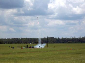
Now that the rocket was finally finished, I got a chance to launch the Escape Velocity at the NEFAR launch in Bunnell, Florida on Saturday, June 14th. NEFAR, the Northeast Florida Association of Rocketry, enjoys a large expanse of beautiful green sod just northwest of Daytona, and the Escape Velocity was ready for its maiden stroll.
For propulsion, I used a AMW/Pro38™ 400I195RR Red Rhino, one of the new red reloads, an I195, that is a result of the Animal Motor Works/Cesaroni Technology Incorporated marketing agreement announced last year. If you haven't flown a CTI or AMW/Pro-X™ motor before, I can't begin to explain how simple these motors are to assemble. You stick it in, screw it down and set the delay. They really are "a better way to fly."
I had some issues with the ACME conformal rail guides that came in the kit not wanting to stay where I put them, but then again I only relied on the enclosed double-edged tape supplied with the guides to attach them. That was a short-lived problem, as a dose of medium CA firmed things back up in short order. Back at the pad, the rocket was loaded onto the rail and the igniter installed. A quick twist armed the RRC2-Mini, and it beeped a happy, armed-with-continuity song.
When the button was pushed, the AMW/Pro38 Red Rhino came to life and took the Escape Velocity on a rapid trip, before the Missile Works RRC2-Mini gently performed its services in its ubiquitous manner, lowering the rocket in a beautiful dual deployment display. When I arrived at the rocket, the RRC2-Mini was beeping out 2703 feet, a beautiful flight of a great kit. With the dual deployment and my fiberglass reinforcement, this rocket can easily take the biggest 38mm motors available and keep coming back for more.
If you are looking for a great level one and even level two certification rocket, it's hard to go wrong with the Escape Velocity. I know, because my flight was also my level one re-do after being out of the hobby for so long. And when I say the kit has everything you need except a motor and launcher, I really mean it. Well, ok, you have to supply some epoxy, but I figured you could handle that! Try an Escape Velocity, you'll be very satisfied with the kit.
You can check out the Escape Velocity on the Giant Leap Rocketry site at http://www.giantleaprocketry.com/.
Editor's note: The author has since flown the Escape Velocity yet again, this time for his TRA level two certification, using an AeroTech J350W, to reach an altitude of 5086 feet. The launch took place at NEFAR's July 12th launch in Bunnell, Florida. The Escape Velocity never missed a beat, took the abuse and came back ready for more. This kit is a serious certification rocket not to be overlooked.
Other Reviews
- Giant Leap Rocketry Escape Velocity 2.6 By Bryan Sparkman (February 16, 2007)
Brief: The Escape Velocity is a single stage, high power, dual or single deployment rocket for 38mm motors or 29mm with an adapter. Construction: The Escape Velocity came with everything you could want for a HPR rocket and more. Included were 1 pre-cut phenolic body tube, 1 phenolic payload tube, fin can, payoad bay, 1 18" drogue parachute, 1 36" main parachute, ...

 |
 |
Flights
|
|