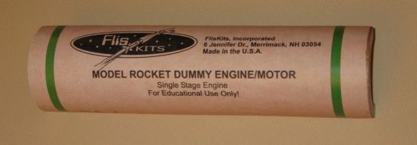
FlisKits Cut-Away Motor Rocket Motor
FlisKits - Cut-Away Motor Rocket Motor {Kit}
Contributed by David Landgraf
| Manufacturer: | FlisKits  |
Brief:
If you have ever been at a loss for a giant version of a model rocket motor to use as a teaching aid to hold up in
front of a class, this is your ticket. This little kit provides a good illustration of the internal parts, gives you a
model in a good, usable size, and is easy to assemble in a couple hours of total work time. It requires primarily a
sharp X-Acto knife and some Elmer's-type white glue.
Construction:
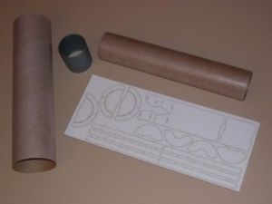
When I first opened the kit, I was impressed with the high quality of the laser-cut sheet, both the material and the
laser work. The sheet material from which components were cut was a cardboard-type product that was very light while
still having good strength and stiffness. The faces of the sheet were finished with a "plastic" layer that
made me think of the exterior of Estes-style body tubes. The laser-cut lines were (to me) very narrow (0.1 to 0.2 mm?)
but were straight, neat, and without any noticeable scorch marks on the surrounding material. Parts were connected to
the main sheet by tiny webs that were easily severed with the tip of a sharp X-Acto knife. Parts fit so snugly within
the sheet that a little patience and care was needed to separate them without damaging the edges of the parts.
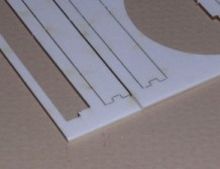
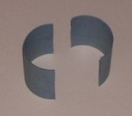
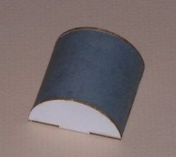
Before separating any parts from the laser-cut sheet, it would be good for the builder to check and make a clear identification of all parts before separating them. Builders should note that the spine is slightly different from the two casing caps (and may want to pencil a label on the parts to note which is which). Similarly, the four nozzle parts (the half-disc-shaped items down the center of the sheet) should be noted and identified. It is not difficult to see a difference between the nozzle 1/nozzle 3 parts and the others because 1 and 3 have a large center cutout (and if I am not mistaken, nozzle 1 and nozzle 3 are the same size and interchangeable). The most important difference is that nozzle 2 has a small center cutout and might be mistaken for nozzle 4 if the builder gets in a hurry.
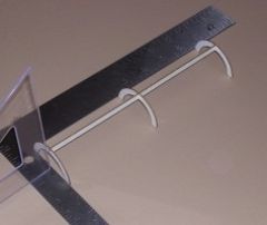
 For Step 2, the builder must remove the spine, casing caps, and ribs from the
laser-cut sheet. These parts should be handled carefully as they are relatively delicate until they are assembled. It
is easy, for example, to bend the long, thin, narrow spine and casing caps, but they need to be quite straight for this
kit to work. It might be a good idea for the builder to separate these parts by cutting the connecting sprues, then
place the sheet on a flat cutting surface for support and cutting away the surrounding sheet material from one end.
This makes it much easier to remove these parts gently from the rest of the sheet and keep them straight.
For Step 2, the builder must remove the spine, casing caps, and ribs from the
laser-cut sheet. These parts should be handled carefully as they are relatively delicate until they are assembled. It
is easy, for example, to bend the long, thin, narrow spine and casing caps, but they need to be quite straight for this
kit to work. It might be a good idea for the builder to separate these parts by cutting the connecting sprues, then
place the sheet on a flat cutting surface for support and cutting away the surrounding sheet material from one end.
This makes it much easier to remove these parts gently from the rest of the sheet and keep them straight.
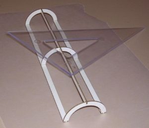
I found the four parts needed for Step 2 and checked them for flatness and clean edges. I used only a very small amount of glue to assemble each rib to the spine; a dot of glue from the tip of a toothpick was enough to prep each connecting joint. Large amounts of glue are really not necessary at this point (or at any point in this kit) and would just make a mess. The parts are pre-cut with tabs and slots, and the fit was very good.
 I had no difficulty completing Step 2 but worked quickly (before the glue dried
completely) and checked for proper part alignment by placing the finished assembly upside down on a good flat surface.
All six rib tips should sit squarely on the flat surface. I also used a framing square (two tablets of paper could also
form a 90 degree corner) and a plastic triangle to check that the end ribs were square and the spine was straight. I
handled this thing very carefully to set it aside, and let it dry while working the next steps.
I had no difficulty completing Step 2 but worked quickly (before the glue dried
completely) and checked for proper part alignment by placing the finished assembly upside down on a good flat surface.
All six rib tips should sit squarely on the flat surface. I also used a framing square (two tablets of paper could also
form a 90 degree corner) and a plastic triangle to check that the end ribs were square and the spine was straight. I
handled this thing very carefully to set it aside, and let it dry while working the next steps.
In Step 3, the nozzle pieces and the propellant plate are assembled. Again, I used the tip of a toothpick to apply glue to the joints, this time because I wanted to be able to adjust them a bit (if needed). I used my plastic triangle again to check alignment, but the corner of a business card or any small object with a square corner could be used. It was easy to clear the waste material from the pre-cut slots and I found the pre-cut tabs fit cleanly and firmly into the slots. (Jim, have you given any thought to completely cutting these slots, with no sprues, so the tiny little pieces just fallout?) Once these parts are properly assembled, the builder can add more glue but it really isn't needed.
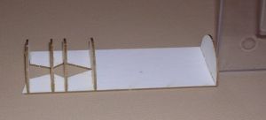
 For Step 4, the two casing caps are added to the edges of the assembly from
Step 2 (the delicate one). The casing caps appear to be symmetrical and can be turned either way and will still fit
properly. I used my trusty toothpick to place a small dot of glue on the tips of the ribs and spread it across the
joint. I worked quickly to complete this assembly and re-checked everything with my framing square and plastic
triangle, trying to keep everything square during and after handling these delicate parts. Finally, I placed the
assembly upside down on a flat surface and laid a light object (the plastic triangle) across to top to gently hold all
the parts in alignment while the glue dried. Let the glue dry thoroughly; do not proceed if this rib assembly is
"soft" or loose.
For Step 4, the two casing caps are added to the edges of the assembly from
Step 2 (the delicate one). The casing caps appear to be symmetrical and can be turned either way and will still fit
properly. I used my trusty toothpick to place a small dot of glue on the tips of the ribs and spread it across the
joint. I worked quickly to complete this assembly and re-checked everything with my framing square and plastic
triangle, trying to keep everything square during and after handling these delicate parts. Finally, I placed the
assembly upside down on a flat surface and laid a light object (the plastic triangle) across to top to gently hold all
the parts in alignment while the glue dried. Let the glue dry thoroughly; do not proceed if this rib assembly is
"soft" or loose.In Step 5, the BT-60 is finally glued to the inside of the rib assembly from Step 4. I think the best way to glue this whole thing together is to use only small amounts of glue on the inside of the rib framework for the initial assembly to the BT-60. This way the glue dries quickly, and if the framework needs to be repositioned, it will not be as difficult to cut through all the glue joints. Once the rib framework is in place, the builder can add more glue to all the joints, but more glue should only be added to the "framework" side but should be kept clear of the opposite side to make life easier in following steps.
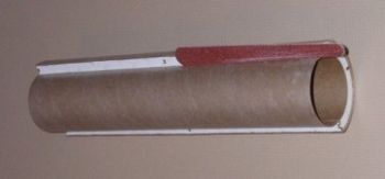
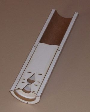
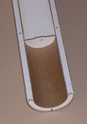
For Step 9, the assembly from Step 5 will be glued into the wider of the two pieces of BT-70 from the previous step. In order to get a good glue bond in the middle of this thing, I used an end rib as a marking guide and made a pencil mark where the center rib would touch the inside of the BT-70 so I could apply glue while this area was still open. Note the Q-tip that was used to spread out the glue.
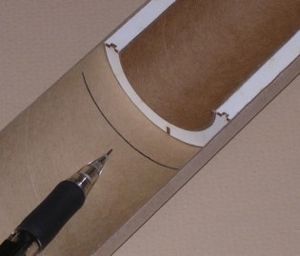
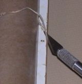
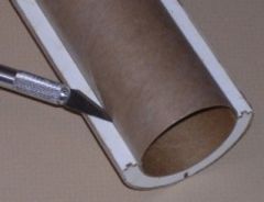 In Step
11, the builder will make the same kind of cut but will trim the inner BT-60. Again, hold the X-Acto cutting edge at a
shallow angle, make several passes, and the BT-60 will soon cut through.
In Step
11, the builder will make the same kind of cut but will trim the inner BT-60. Again, hold the X-Acto cutting edge at a
shallow angle, make several passes, and the BT-60 will soon cut through.In Steps 12, 13 and 14, follow the directions. Jim already has these well described. I might add that Step 13 is another place where a small amount of glue, applied by toothpick, will be plenty to attach and hold the caps onto the ends of the delay plate. (And a small amount of glue gives a second chance to adjust the position of the caps, if necessary.) Step 14 is another wraparound marking guide that is sized for the CPL60 coupler and has uneven marks just like the guide used for Step 6. Builders will end up with two sections of coupler that are two slightly different widths...and they are supposed to be that way.
 The
CPL60 coupler material was much easier to cut than I expected (going from past experience with Estes coupler material).
It is still necessary to make several light passes and cut progressively deeper each time, just as when cutting body
tube cardboard, but the FlisKits CPL60 material is only slightly tougher to cut than the BT-60. Builders should have no
trouble completing these cuts, but should observe all normal safety measures when using an X-Acto knife.
The
CPL60 coupler material was much easier to cut than I expected (going from past experience with Estes coupler material).
It is still necessary to make several light passes and cut progressively deeper each time, just as when cutting body
tube cardboard, but the FlisKits CPL60 material is only slightly tougher to cut than the BT-60. Builders should have no
trouble completing these cuts, but should observe all normal safety measures when using an X-Acto knife.
 In Step 16, one of the cut pieces of CPL60 is glued to the delay plate assembly from Step
13. When I built my preliminary version of this model kit, this assembly was designed slightly differently from the
final production version. It was still closely representative of the delay assembly, which is an optional part of the
motor model that represents the delay and ejection charges and end cap retainer for single stage and upper stage
motors. If this assembly is removed from the model, it illustrates a booster motor loaded only with propellant.
In Step 16, one of the cut pieces of CPL60 is glued to the delay plate assembly from Step
13. When I built my preliminary version of this model kit, this assembly was designed slightly differently from the
final production version. It was still closely representative of the delay assembly, which is an optional part of the
motor model that represents the delay and ejection charges and end cap retainer for single stage and upper stage
motors. If this assembly is removed from the model, it illustrates a booster motor loaded only with propellant.
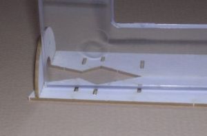
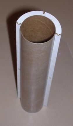
And speaking of propellant, this is the point where I inserted the propellant plate assembly (from Step 3) into the aft end of the motor case assembly (from Step 12). Because the fit of these two assemblies was so snug, I was concerned about my ability to slide them together with glue already applied and get them properly positioned before the glue "grabbed" and locked them in the wrong position. So, I assembled them dry. I placed the propellant plate assembly about 1/4 inch forward of the aft edge of the motor case assembly because most black powder motors have the ceramic nozzle stamp-formed a short distance inside the back end, not flush with the end of the motor case. I pressed the propellant plate into the motor case assembly until the outer face sheet made a flush fit with the casing caps. After the propellant plate was seated where I wanted it, I was able to apply glue through the openings in the propellant plate and around the aft nozzle part. I also applied a thin bead of glue around the front propellant end cap, but builders should avoid using a thick fillet at the front cap so that the delay plate assembly will be able to fit.
Getting close to the end: I think that soaking a few drops of CA (cyanoacrylate, or "superglue") into the outside corners of the motor case model would greatly improve the durability of this model. If handled with reasonable care, this model will probably stand up well to handling, transport, and other demands, but I think it couldn't hurt anything to use a touch of CA for an extra bit of reinforcement on the corners.
Finishing:
I should point out that this model really does not require any painting at all, but was my own choice. (Yeah, I'm one
of those obsessive-compulsive people that likes to add my own little extra touches.) The motor model works just fine
without any paint at all. I applied a thin layer of spackle to the "show" face of my model and sanded it
smooth (and mostly removed) before proceeding with primer and paint. I think this just makes the appearance of the
whole model a little more slick, and it makes a little better surface to apply paint and paper wraps. Any sort of
normal water-based spackle from the local hardware store can be used. Use 400 or 600 grit sandpaper to smooth the
surface, wipe any remaining dust off the surfaces for better paint adhesion, and use appropriate colors. I ended up
using a combination of tan and medium brown to get an authentic "cardboard" color. I also masked off the
areas around the nozzle and used a gray spray paint to color the nozzle surfaces that the paper wrap would not cover.
In hindsight, all this priming and spray painting was probably more work than it was worth--I will probably just use
brown and gray highlighters next time.
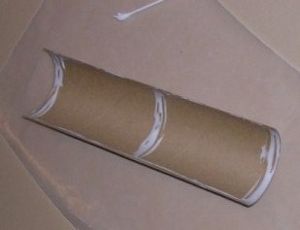
The paper wraps were assembled using Duro All-Purpose spray adhesive on the back face of the paper and on the matching areas of the motor model. (There are other brands such as 3M spray adhesive that will also work.) I masked the model to prevent getting the spray all over areas where I didn't want it, but all I had to do was mark the edges of the area with masking tape and then tape on some sheets of paper surrounding this area. As always, after spraying both surfaces with adhesive, you have to align the joining pieces very carefully before letting them touch. I thought I got the outer paper wrap just a teeny bit crooked--my wife (an actual full time classroom teacher) said that it was just fine. The inner paper wrap went on very easily and fit the nozzle edges well. The paper wrap for the delay and ejection charge was a little mis-sized for the model I built, but I think that was because I had a "production" wrap and a "beta" model that were a different size.
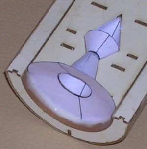
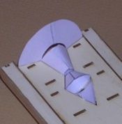
Summary:
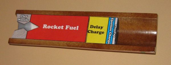
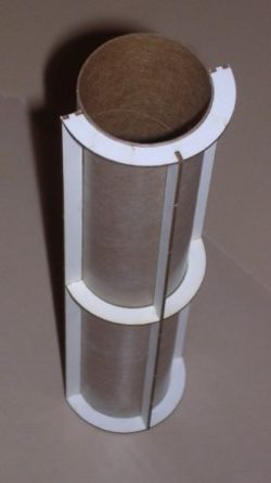
The completed motor model is very scale-like in appearance and should go a long way toward answering questions from
new rocketeers about what is inside the motor. The wraps are designed with bright colors to highlight the important
components and also have good labels for internal parts. All internal components are separately represented (even the
clay cap over the ejection charge) so there is something to point to when explaining any part of the motor's operation.
The removable delay/ejection part is an excellent way to show how booster motors function. The model is designed to a
good size that works very well for talking around a table or for standing in front of a classroom.
Since I made this beta build, FlisKits has added a matching demonstration model of a model rocket igniter. This looks like a great tool for illustrating the parts of an igniter, how to use it, and how to handle it properly.
I don't have one of these yet but it is definitely on my "go get" list.
Overall, I think part quality and fit is very good in the new FlisKits motor model. Instructions are clear and follow a logical approach, matching illustrations are very good, and beginners and inexperienced modelers should have no trouble building this motor model. Not being a "flight" model rocket, this kit automatically becomes much more forgiving of misplaced (or left out) glues, and does not require some of the more intricate assembly and heavy-duty adhesives of flying rockets. Undoubtedly, some wise guy will insist this kit must be fiberglassed...just wait and see.
Other Reviews
- FlisKits Cut-Away Motor Rocket Motor By Jim Bassham (March 8, 2009)
( Contributed - by Jim Bassham - 03/08/09) Brief: This is FlisKits' new model of a cut-away rocket motor. It is designed to be used as a classroom or science-fair demonstration model. Construction: The kit consists of a laser-cut sheet of fiberboard parts, two body tubes, a coupler tube and a sheet of paper parts. OK, I really wanted to like this kit, but it was frustrating ...
- FlisKits Cut-Away Motor Rocket Motor By Chan Stevens (February 7, 2009)
( Contributed - by Chan Stevens - 02/07/09) Brief: This is a neat display of the interior of a model rocket motor, and at 3:1 upscale, it's large enough to use in a typical classroom presentation. Construction: This kit comes packed in a typical rocket baggie with color header card and contains the following parts: BT-70 tube Laser-cut cardboard detail sheet ...
- FlisKits Cut-Away Motor Rocket Motor By Hans "Chris" Michielssen (February 1, 2009)
( Contributed - by Hans "Chris" Michielssen - 02/01/09) Brief: I "won" this kit on a rocketry forum. A build thread hosted by Powderburner followed the steps of the assembly. After the last assembly post, the host asked the readers to find the mistake in his build. If you found the error you would receive a Cutaway Engine Kit as a prize. I read through the ...
 |
 |
J.F. (March 21, 2009)
* This model is not aimed at young modelers and is certainly not what we would call a beginner kit. You are correct that there are challenges in building it.
* The cost point we were aiming for (less than $10) precludes us from including a label with the kit. A free download label is easy to provide and is only an available option. the builder is free to finish it as they choose.
* I would be most interested in working with you offline as your comments about difficulty in removing laser cut parts and a flimsy end product indicate that you may have gotten some defective parts as you shouldn't be having such problems. Feel free to contact me if you would like some resolution in this regard. Thank you for your review. As you know we value all feedback and negative feedback helps us identify things that need attention!
|
|
R.A.M. (January 22, 2009)