| Manufacturer: | Public Missiles  |
Note: This is a slightly condensed version of all the information that Frank has produced for his Level 3 project. Visit the Tripoli Netherlands site (look under Projecten) to read the additional information and enjoy additional pictures.
 I decided to fly a Level 3 rocket
at ALRS 1 in Switzerland on the 24th and 25th of March 2000. After contact with
Juerg Thuering, the Prefect of Tripoli Switzerland and also one of the TAP
members to evaluate the project and flight. I decided that my intended flight
of Ignis Volans Gamma Mark II on a M1315 would have problems with the waiver
that was granted up to 7600', the IVGMII would reach at least 14000' so that
flight was out of the question. Now I had a M1315 casing, a reload in
Switzerland, but no rocket to fly it during ALRS 1. After a week of pacing
around and rethinking the possibility's, from rearward ejection up to building
the Ignis Volans Epsilon (which is planned for next year), or a Nike Smoke, I
always found a major problem. Rearward ejection would take place at 450 km an
hour, well those rocketman-reinforced drogues are strong, but if an airframe
would be able to withstand the forces if the drogues deployed to stop the
rocket before the ceiling was reached.....The parts for the Nike and the
Epsilon were all still somewhere on a boat across the North Atlantic, so that
gave me a definite time problem as ALRS 1 was still 60 days away.
I decided to fly a Level 3 rocket
at ALRS 1 in Switzerland on the 24th and 25th of March 2000. After contact with
Juerg Thuering, the Prefect of Tripoli Switzerland and also one of the TAP
members to evaluate the project and flight. I decided that my intended flight
of Ignis Volans Gamma Mark II on a M1315 would have problems with the waiver
that was granted up to 7600', the IVGMII would reach at least 14000' so that
flight was out of the question. Now I had a M1315 casing, a reload in
Switzerland, but no rocket to fly it during ALRS 1. After a week of pacing
around and rethinking the possibility's, from rearward ejection up to building
the Ignis Volans Epsilon (which is planned for next year), or a Nike Smoke, I
always found a major problem. Rearward ejection would take place at 450 km an
hour, well those rocketman-reinforced drogues are strong, but if an airframe
would be able to withstand the forces if the drogues deployed to stop the
rocket before the ceiling was reached.....The parts for the Nike and the
Epsilon were all still somewhere on a boat across the North Atlantic, so that
gave me a definite time problem as ALRS 1 was still 60 days away.
So on 24 January 2000 I decided to built the following project, as it would be a great pity not to use that M1315 motor at ALRS 1 (Aerotech with serial NR. 13 !). I had planned to built a PML Pterodactyl this year for the launch in July at the ASK in the Netherlands. So the following plan developed after allot of designing in RockSim 4.0 and mailing with Juerg Thuering. The Pterodactyl has a good airframe for a Level 3 flight but needed some ''small'' adjustments:
Conversion from PML kit to Level 3 M.
- Replace the 54mm motormount with a 75-mm motormount and attach a Aero Pack Quick Change Motor Retainer.
- Reinforce the through the wall fins with aircraft plywood for strength along the roots of the fins that would be in the Booster Section.
- Coat the whole airframe with 2 layers of Epoxy and Kevlar.
- Replace the launch lugs with BlackSky Aluminum rail guides.
- Extend the Airframe by 48'' to make room for a Rocketman R18C Experimental Main Chute, a Reinforced Rocketman Drogue Chute RHDC , the AED RDAS Main and BlackSky AltAcc Backup Computers. Called Chute Section and Coupler - Avionics Section.
- Built a compartment into the Nose Cone for extra weight placement. Called Weight Section.
- Design a Main and Drogue Chute Section with Piston ejection for the Main Chute.
 After contacting
PML for the parts, Fedex arranged the delivery on the 5th of February with help
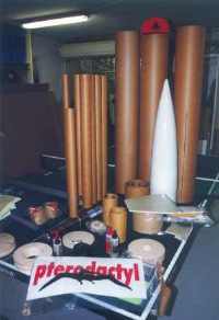
from Peter Fakkeldij, who sent the package. As I had a free day I started with
unpacking and stacking all the parts in our garage on our tennis table. After
wondering about the size I started with the construction. First I dumped the
parts of the PML kit that I would not use into the parts corner of the hobby
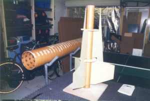
room. As I had just finished the stand for the rocket to rest in, I started
with applying Elmers Wood filler on the 2 main body tubes. After that I
calculated the fin position and trimmed the fins to fit the 75-mm motor tube.
That day I finished the filling of the grooves on the tubes and got all the
fins aligned on the 75-mm motor tube and 2 centering rings attached.
After contacting
PML for the parts, Fedex arranged the delivery on the 5th of February with help
from Peter Fakkeldij, who sent the package. As I had a free day I started with
unpacking and stacking all the parts in our garage on our tennis table. After
wondering about the size I started with the construction. First I dumped the
parts of the PML kit that I would not use into the parts corner of the hobby
room. As I had just finished the stand for the rocket to rest in, I started
with applying Elmers Wood filler on the 2 main body tubes. After that I
calculated the fin position and trimmed the fins to fit the 75-mm motor tube.
That day I finished the filling of the grooves on the tubes and got all the
fins aligned on the 75-mm motor tube and 2 centering rings attached.
Hmmm this rocket had already flown with Fedex up to 35.000 feet at least, wasn't every flying object allot of spare parts flying in close formation?
The next construction day I started with making the reinforcements for the fin attachments from aircraft grade plywood. I Also sanded the Chute Section and applied 2 layers of Kevlar and epoxy resin over it and set it to dry. After the reinforcements had been attached to two fin sides it was covered with one layer of epoxy resin. Then I started with the nose cone. I first made two centering rings to make a 3.90'' Weight Section and made the body tube to the right length. After fitting it into the Nose Cone I attached a bulkhead in the top of the 3.90'' Weight Section and attached the two centering rings. I also made the closure of the Weight Section and attached a U-bolt to it for the recovery harness. The Weight Section will be carrying the extra weight during the flight to get the CG right. After the Chute Section was dry I coated it with another layer of epoxy resin. Then I cut one layer of Kevlar to fit between the fin reinforcement and applied it with a layer of epoxy resin to dry overnight.
 On day three of the
construction I started with fitting the Weight Section into the Nose Cone and
applying epoxy to set it into place. Thereafter I started with the second fin
reinforcements of plywood. After that was set to dry the design of the Coupler
- Avionics Section came next. I started with sorting out the Bulkplates and
Centering Rings and attached the U-Bolt for the Main Chute rigging. It took a
while to sort out the construction order, as the safety plugs location had to
be figured out. Also of importance was that the Avionics Bay for the AED RDAS
and the backup BlackSky AltAcc were to be fitted into the Coupler between the
Booster Section and the Chute Section. The Coupler would be having two
purposes, one to connect the rocket parts together and second to house the
Avionics. Assembly came next after all the measurements were taken and
calculated.
On day three of the
construction I started with fitting the Weight Section into the Nose Cone and
applying epoxy to set it into place. Thereafter I started with the second fin
reinforcements of plywood. After that was set to dry the design of the Coupler
- Avionics Section came next. I started with sorting out the Bulkplates and
Centering Rings and attached the U-Bolt for the Main Chute rigging. It took a
while to sort out the construction order, as the safety plugs location had to
be figured out. Also of importance was that the Avionics Bay for the AED RDAS
and the backup BlackSky AltAcc were to be fitted into the Coupler between the
Booster Section and the Chute Section. The Coupler would be having two
purposes, one to connect the rocket parts together and second to house the
Avionics. Assembly came next after all the measurements were taken and
calculated.
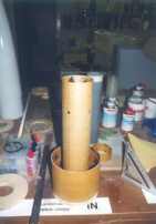
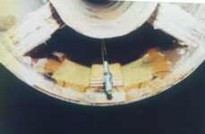
Day four commenced with the last fin reinforcements and a layer of Kevlar and Epoxy Resin to add some more strength. Also for this purpose 3 rods (see picture below) were added to give some extra strength to the Centering Rings. The Coupler - Avionics Section was also further constructed up to the part that it had to wait until the Booster Section would be ready for integration with the Coupler - Avionics Section.
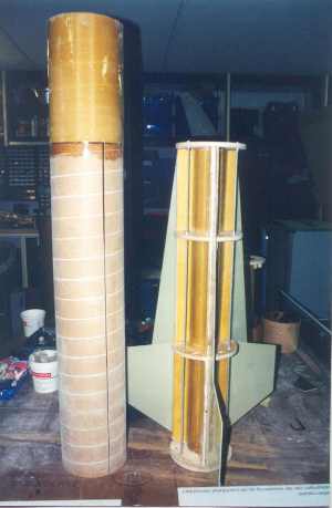 After this the
Booster Tube was joined with the Booster Frame and so it formed the Booster
Section. It started to look like a rocket. A lot of days passed with epoxy and
Kevlar to join the Booster Section together. A thing to plan with this step is
to follow a construction order in which you can make all the Epoxy filaments. I
drilled some holes in the centering rings of the Booster Frame to be able to
apply the Epoxy with some big injection tubes. After every layer or
reinforcement joint, the epoxy had to set and I had to wait for the next step.
In the meantime I made the extra Weight Canister for the Nose Cone and finished
the Piston for the Main Chute. Also the main motor bulkplate was finished and
the motor thrust plate construction. I took a 3.90'' Coupler to act as a Weight
Canister and fitted it with a Bulk Plate and 4 T nuts for attachment. During
the rest of the construction I poured all the excess Epoxy into this Weight
Canister. Later I would adjust the weight for the CG with it or just saw a
piece of to get the right CG adjustment.
After this the
Booster Tube was joined with the Booster Frame and so it formed the Booster
Section. It started to look like a rocket. A lot of days passed with epoxy and
Kevlar to join the Booster Section together. A thing to plan with this step is
to follow a construction order in which you can make all the Epoxy filaments. I
drilled some holes in the centering rings of the Booster Frame to be able to
apply the Epoxy with some big injection tubes. After every layer or
reinforcement joint, the epoxy had to set and I had to wait for the next step.
In the meantime I made the extra Weight Canister for the Nose Cone and finished
the Piston for the Main Chute. Also the main motor bulkplate was finished and
the motor thrust plate construction. I took a 3.90'' Coupler to act as a Weight
Canister and fitted it with a Bulk Plate and 4 T nuts for attachment. During
the rest of the construction I poured all the excess Epoxy into this Weight
Canister. Later I would adjust the weight for the CG with it or just saw a
piece of to get the right CG adjustment.
Then I sanded and sanded. After everything was fitted and sanded ok, two layers of 2 component Epoxy paint were applied as primer.
After the Booster Section was finished the Avionics Section was added to the
Booster Section but first the BlackSky Aluminum Rail guides were attached by
making a reinforcement in the inside of the Booster Tube with T-nuts on the
inside and a layer of Kevlar and Epoxy over the reinforcement. The Coupler -
Avionics Section was further build up with installing the Activation Plugs and
the T-nuts for the connection between the Booster Section and the Chute
Section. Again a series of epoxy pouring and waiting followed. And always
making sure the PML logo on the tubes pointed upward in intended flight
direction, kind of a superstition under Rocketeers.

Then came the next problem. Up until now I had planned to use a piston in
the Chute Section to eject the main chute and to connect the drogue on top of
that with an own ejection charge. The plan was that the drogue charge would
eject the Nose Cone and the Drogue Chute. The Drogue Chute would be attached to
the top of the Piston of the Main Chute. I was thinking of using shear pins to
hold the Piston in place until ejection of the Main Chute. After some
discussions with Juerg Thuering I found out the pins were never going to hold
the Piston in place if the drogue would be attached and pulled on the Piston.
The forces would be too high for this size of rocket. So back to the drawing
board. Juerg came with the idea of using Chute Cannons, well I hadn't thought
about that idea yet. After thinking it over I came to the conclusion that this
would solve my recovery problem.
So a quick glance in my spare corner and out came some parts that would be
needed to build two Chute Cannons. And there went the nicely constructed Main
Piston, into the spare corner. Then the Main R18C Chute from Rocketman arrived
for the TinTin project of Chiel Klijn, and I figured my Chute Cannon of 3.90''
would be way to small to fit my R18C Chute. Rocketman was still making my chute
for me to pick up in the middle of March, so I decided to order some more parts
for a 6.00'' Chute Cannon at PML. Fedex was going to do have some more work.
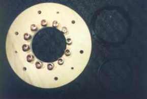
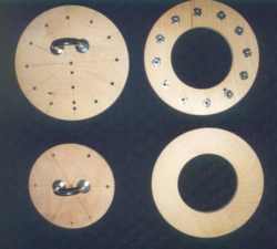
The Aft Bulkhead (above-left) of the Booster Section with the T-Nuts and the Aero Pack Quick Change Motor Mount. Note the rings over the T-Nuts to keep the Epoxy Resin out of the Nuts when adding this over the Centering Ring for reinforcement when it is installed.
While waiting on the last parts I finished the Booster and Coupler - Avionics Section and after a lot of sanding I sprayed the Pterodactyl with a nice finish of Red and Yellow. I also cut new decals as the PML decal had red lettering, and I needed the letters to be white.
The final construction week I paced through my garage, I finished some other rockets and made two field cases for the rockets. At the end of the week, nine days before ALRS 1, the PML parts arrived and I had three days left to finish the Pterodactyl. I also had to visit Ky Michaelson the next week to pick up the Main Chute.
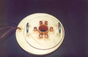
So I started with making the Bulkhead Plate for the Main chute and the Centering Rings for the Main Chute Canon (above-right). I took three Bulkheads and made eccentric 6.00'' holes in them to fit the Main Chute 6.00'' Chute Canon in. The main Bulk Plate I built up using a 7.5'' Bulkplate and one of the Eccentric Rings. In the eccentric hole I placed a 6.00'' Bulkplate for extra thickness and through these two plates I fitted two U-Bolts for the Main Chute Harness connection. Later during the final fitting it came out that the Bolts were too far in the Bulkheads so I glued a Broad line along the 6.00'' Chute Canon and strengthened it with Kevlar. Also I made a hole through the two Bulkplates and fitted a PT-1.525 tube of 25 mm long to act as an Epoxy ring for reinforcement. After this done I made a Bulkhead for the SafeEject EX from a 5.5'' Bulkplate, connection to the Main Chute Bulkhead was done by 6 M4 T-Nuts.
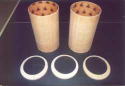 This
done the 6.00'' tube was cut to 700 mm and glued into the Main Chute Bulkhead.
The first Liner was glued on the Main Chute Bulkhead and Epoxy Resin was poured
between the Liner and the Main Chute Tube, and onto the Main Chute Bulkhead for
extra strength. After this done an Eccentric Ring was placed on the first Liner
and glued with 5 minute Epoxy. A second Liner was inserted and glued using
Epoxy Resin. Between the Liner and the Main Chute Tube another amount of Epoxy
Resin was poured in for extra strength. Then the last Eccentric Ring was fitted
with 2 T-Nuts for attachment of the SafeEject and a U-Bolt for the Drogue
Harness. Also the 4 wires for the activation of the SafeEject were run between
the Liners and the Main Chute Tube. The last Eccentric Ring was Glued on and
set to dry. After this done a layer of Epoxy Resin was poured into the top
Eccentric Ring, between the Liner and the Main Chute Tube for extra strength.
Gluing two Bulkplates together and fitting it with an Eyebolt made the lid of
the Main Chute Tube.
This
done the 6.00'' tube was cut to 700 mm and glued into the Main Chute Bulkhead.
The first Liner was glued on the Main Chute Bulkhead and Epoxy Resin was poured
between the Liner and the Main Chute Tube, and onto the Main Chute Bulkhead for
extra strength. After this done an Eccentric Ring was placed on the first Liner
and glued with 5 minute Epoxy. A second Liner was inserted and glued using
Epoxy Resin. Between the Liner and the Main Chute Tube another amount of Epoxy
Resin was poured in for extra strength. Then the last Eccentric Ring was fitted
with 2 T-Nuts for attachment of the SafeEject and a U-Bolt for the Drogue
Harness. Also the 4 wires for the activation of the SafeEject were run between
the Liners and the Main Chute Tube. The last Eccentric Ring was Glued on and
set to dry. After this done a layer of Epoxy Resin was poured into the top
Eccentric Ring, between the Liner and the Main Chute Tube for extra strength.
Gluing two Bulkplates together and fitting it with an Eyebolt made the lid of
the Main Chute Tube.
All the wires were fitted with Deans Connectors and the decals were added on the Booster. Also the BlackSky Aluminum Rail Guides were installed and the Chute Harnesses were made for the Main and the Drogue Chute. The Aero Pack 75 mm Quick Change Motor Retainer was installed as a last construction action.
After this done everything was test fitted and the whole Rocket was assembled for the first time. I tested all the wires and the setup for the RDAS and AltAcc and checked the CG and the Weight of the Rocket without the motor casing. This I checked with the RockSim data and to get the CG right. I found out I would not need the Weight Section for adjustment of the CH, the Rocket checked out fine between 1 to 2 for CG / CP. I marked the CP on the Rocket and found it was time to pack everything for the trip to Switzerland.
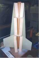
 The following
text goes over the drawing and explains in detail the construction of
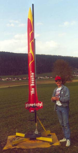
Pterodactyl ''the Beastie''
The following
text goes over the drawing and explains in detail the construction of
Pterodactyl ''the Beastie''
Most parts are PML.
Booster Section
The Booster Section is build up over a PT-3.002'' PML Phenolic Tube that acts as a Motor Housing for the Aerotech M1315. In the top of the Motor Housing there is a Motor Block constructed of 2 BP-05 Bulkplates and a CT-3.00 Coupler Tube. This Motor Block is glued in the Top of the Motor Housing. The Motor Housing has been fitted with 4 Centering Rings to connect to the Main Booster Tube, this is a 48'' PT-7.512 PML Phenolic Tube. The Fins are G10 material and fitted through the main Booster Tube through one long slot to the Motor Housing. On every side of the Fins there is a Strengthening Plate of Aircraft Grade Plywood. These plates run from Centering Ring to Centering Ring and are coated with a layer of Kevlar over the Strengthening Plate, over the Motor Housing up to the next Strengthening Ring. This has been coated twice with 2 Component Epoxy Resin. From the Top Centering Ring to the Bottom Centering Ring run 3 M5 Rods for extra strengthening. Every Centering Ring has been fitted with 2 washers, a tightening spring and 2 nuts where the M5 rod passes through. The outer skin of the PT-7.512 Main Booster Tube has been filled with Elmer's Wood filler to get an even skin and fill the grooves. Over these 2 layers of Kevlar and 2 Component Epoxy Resin have been applied. For extra strengthening and Flutter Resistance the Fins have been covered with an extra layer of Kevlar and 2 Component Epoxy Resin. The 2 main layers of Kevlar run over the whole fin, then over the Body Tube and on to the next Fin. The Bottom Centering Ring and the Top Centering ring have been extra strengthened with a layer of 5 mm 2 Component Epoxy Resin. The Area between the Motor Housing and the Body Tube vents to the outside via 3 holes between the Fins. The Bottom Centering Ring has been fitted with an Aero Pack 75 mm Quick Change Motor Retainer. On 3 places the Body Tube has been fitted with Strengthening Plates of Aircraft Grade Plywood with T-nuts of 4 mm which connect to 3 Aluminum BlackSky Rail Guides. The Plates are glued to the Main Body Tube with 5-minute Epoxy and after a layer of Kevlar with 2 Component Epoxy was added for strength.
Coupler-Avionics Section
The Coupler-Avionics Section is built up into the Booster Section. First a PT 3.90'' tube was glued to a 7.50''-3.90'' Centering Ring of Aircraft Grade Plywood and this on to a 7.50'' Bulkplate. On this construction a 7.50'' Coupler was glued and several static portholes were made in the PT-3.90'' tube. Also a special hole for the Activation Cables is made. Into the PT-3.90'' tube a 50 mm long Coupler was glued to support the Avionics. After this a layer of Epoxy Resin was poured on the Bottom between the 7.50'' Coupler and into the 3.90'' tube for strength. The whole assembly was fitted into the Booster and glued with Epoxy Resin on top of the Motor Housing. Into the 3.90'' tube the cables and the Activation Plugs in the Booster Section are installed. Also an third BlackSky Aluminum Rail Guide is installed using the same method as above. Another 7.50''-3.90'' Centering Ring was lowered into the Section and installed. On top of this CR a second 7.50'' Coupler is installed and an extra layer of Epoxy Resin added between the Coupler and the PT-3.90'' tube. Into this 7.50'' Coupler all the holes for connecting the Booster Section to the Chute Section and the Static Ports are drilled. 6 Plates from Aircraft Grade Plywood are fitted around the 7.50'' Coupler with each 3 M4 T-Nuts to attach the Booster Section to the Chute Section. A 7.50''-3.90'' Centering Ring with 12 T-Nuts is glued on top of the Booster Section and an extra layer of Epoxy Resin is added in this Section to set it into place while the Booster Section stood on its head. On top of this a Closing Plate protects the Avionics Bay. The Avionics Bay has two more 3.90'' 50mm long Couplers, which separate the 2 Avionics Sections.
 Chute Section
The Chute Section exists of a PT-7.50'' 48''long Phenolic Tube which was filled with Elmers Wood Filler into the grooves, then two layers of Kevlar were applied with Epoxy and over that an extra layer of Epoxy. Into this Tube a 7.50'' Centering Ring of 50 mm long was positioned on the bottom to fit onto the Coupler-Avionics Section. The Chute Section itself is built onto that. It exist of a 7.50'' Bulkplate with an Eccentric 7.50''-6.00'' Centering Ring onto that. In the Centering Ring a 700-mm long PT-6.00'' tube forms the Main Chute Section and on the Bottom a 6.00'' Bulkplate is installed for extra reinforcement of the first 7.50'' Bulkhead, as it will act as connection for the Main Chute Harness. This is further positioned with two more Eccentric Centering Rings and two pieces of 7.50'' Coupler Tubing in between. The whole assembly is glued into the PT-7.50'' tube and extra layers of Epoxy Resin added on the Eccentric Centering Rings for strength. The Main Chute Harness is attached to a Harness Line that is Glued to one side of the 6.00'' Chute Tube and strengthened with Kevlar. Two Safe Ejects are fitted for activation of the Main Chute. The Safe Eject is mounted on a Small Bulkplate that fits in a hole in the two Main Bulkheads and is connected by six M4 screws in 6 T-Nuts in the Main Bulkheads. The Main Chute is a Rocketman Pro-Experimental R18C and a Nomex HiTek Flame Shield protects this chute. On top of the Main Chute Section is a lid from two 6.00'' Bulkplates that protects the Main Chute from the Drogue Chute activation. This plate is connected to the Main Chute Harness for recovery. Through the double wall run 4 wires for the Drogue Chute activation to a Safe Eject on the last 7.50''-6.00'' Eccentric Centering Ring. To the side of this Safe Eject is a U-Bolt for the connection to the Drogue Chute. The Drogue Chute is a Rocketman R7C / R9C or two Reinforced Drogue Chutes depending on the wind on the Launch Site. The Harness of the Drogue Chute is connected to the U-Bolt on the Nose Cone Section. The Drogue Chute is again protected by a Heat Shield and the Lines are Nomex Covered.
Nose Cone Section
The Nose Cone Section exists of a 7.50'' Glass Fiber PML Nose Cone with a PT-3.90'' tube glued into it with a 3.90'' Bulk Plate on top. The 3.90'' tube is centered by two 7.50''-3.90'' Centering Rings and a 6.00'' Bulkplate, attached by 6 4 mm T-Nuts and Bolts, closes it. Into the 3.90'' tube a 3.90'' Coupler is fitted with a Bulkplate underneath and 4 M4 T-Nuts into it for connection to the 6.00'' Bulkplate. The 3.90'' coupler is filled with epoxy resin to act as balancing weight for positioning the CG on the right spot for Flight. Into the 6.00'' Bulkplate a U-Bolt is installed for connection to the Drogue Chute.
Finishing
The whole Rocket has been primed twice with 2 Component Epoxy paint and a layer of Epoxy Filler in between. 5 Coats of Paint did the rest. And of course a lot of sanding between all the layers.
Recovery
A Drogue Chute on Apogee will recover Pterodactyl ''the Beastie''. Activation will be by RDAS or by AltAcc, whichever senses the Apogee first. The Nose Cone Section will be ejected and will fall under the Booster-Chute Section by a long line. At 600 meters the Main Chute will be activated a will lower the descent to a safe value. The Main Chute Harness will extend beyond the Drogue Chute and the Nose Cone will stay under the Booster-Chute Section.
 SUCCESSFUL LEVEL 3 FLIGHT!
March 25, 2000
ALRS 1 Launch - Switzerland
Rocket - Modified PML Pterodactyl - "The Beastie"
Weight - 66 lbs
Motor - Aerotech M1315
Altitude 4384 feet
When we (then ''future'' and now Tripoli the Netherlands) arrived at ALRS 1 (the first big Launch Campaign of HPR rockets in Europe), Juerg Thuering the Swiss prefect, told us we had to go for a launch that day, because the weather would turn on us the next day. So we all unpacked and started prepping feverishly. As I still had to do my successful Level 2 flight with a prefect witnessing it, I started with my redesigned Ignis Volans Gamma. After 90 minutes or so I was ready and launched the Ignis Volans for a perfect flight and recovery. Juerg signed me of and handed me the M1315 reload for the Pterodactyl. Now I had something to do....
First I'll tell something more about ALRS 1. Tripoli Switzerland was the organizing Prefecture and did a good job. About 30 to 40 flyers from all over Europe had gathered near Neuchatel and were all prepping their Rockets and looking forward to a great day. The weather was excellent, blue skies and the sun shone on our necks the whole day, as we noticed back in the hotel due to sunburn. ARGOS, the Advanced Rocket Group of Switzerland (Tripoli Swiss is part of this) had chosen a nice spot up in the mountains of Switzerland. There were 5 pads available, 2 low power, 2 high power and a heavy high power pad. The whole day, and the next afternoon a total of about 50 rockets were launched and recovered, although the recovery didn't always go to plan, it still is the most difficult part of the flight. In the evening there was a nice flyers dinner with a raffle with prizes from the sponsoring Vendors. In my opinion HPR is growing fast here in Europe so we'll have some nice launches to see forward too. A lot of pictures from ALRS 1 can be found at www.stabilit.ch/argos/ and on this homepage
But now back to the Pterodactyl. I had planned to fly it with a RDAS as main Altimeter and an AltAcc as backup. Juerg had sent me an AltAcc, but it never arrived. One week before the launch he had sent me another one, but that one tough mailed by express, hadn't made it also. Weeks later the second package arrived at my home and Juerg found out the first one was returned to his address....
So I had a problem with taking care of the backup for the RDAS. Luckily
Bert Koerts had a RDAS to spare, so with some improvisation I was able to use
this as a backup altimeter. Flying with 2 RDAS computers proved to be a good
choice as no one had done this before, and so I was able to compare the both on
results. Which proved the RDAS is just the best system there is as you can see
in the graphs further on, especially with all the extension boards that are
being developed.
It took me nearly 3 hours to rig everything into the Rocket and during the
prepping, Rolf Orell (the Prefect of Tripoli Sweden) examined the Pterodactyl
''the Beastie'', went through my pre-flight file and asked allot of questions
why I had done this and that. Juerg Thuering had done this as TAP member during
the building and Rolf checked the Pterodactyl out before the flight, as TAP
member.
During the prepping allot of people came by and asked allot of questions, I really had to stick to my checklist, not to forget anything and making no mistakes while prepping.
 Finally the
Pterodactyl ''the Beastie'' was ready for flight, so with help from the
Netherlands Team I moved the Rocket to the Pad. Here I placed the Pterodactyl
together with the Netherlands Team on the Pad X-ray. I activated the two RDAS
computers, inserted the igniter and took some last pictures. Then there was a
problem with the Launch Box, one of the relays was burned in, so another Launch
Box was set up and the Pterodactyl was ready to go.
Finally the
Pterodactyl ''the Beastie'' was ready for flight, so with help from the
Netherlands Team I moved the Rocket to the Pad. Here I placed the Pterodactyl
together with the Netherlands Team on the Pad X-ray. I activated the two RDAS
computers, inserted the igniter and took some last pictures. Then there was a
problem with the Launch Box, one of the relays was burned in, so another Launch
Box was set up and the Pterodactyl was ready to go.
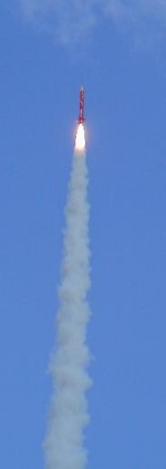
The silence run through me, I am always a bit stunned before a flight when it is something I fly for the first time. You have to let it go then, it is out of your hands. One small mistake can ruin every flight in my opinion. The LCO made a speech and the countdown started. It seemed like eternity. I guess nobody really knew what to expect except Juerg Thuering and Rolf Orell. Then the countdown wound down and the igniter was activated, the M1315 ignited with a blast and Pterodactyl ''the Beastie'' flew straight of the BlackSky Rail up into the blue sky with a roar and under a oval of fire, the flight was perfect and straight (You can download the MPG on request from debro@inorbit.com).
At apogee the drogue deployed and ''the Beastie'' came falling down to earth under cheers of the public. At 200 meters the RocketMan main chute deployed and ''the Beastie'' made a nice landing. Wow what a flight that was.
After that everybody congratulated me and I was muted for a week. When I got the video of the Launch everything came back, so now I have a plan for LDRS 2001, but you will hear about that another time. I will only say for now that the Rocket will be named Northern Light and it will be M powered at least.
Other Reviews
- Public Missiles Pterodactyl By Joel Simon
Brief: Single-staged HPR rocket, built for Level 2 certification. Piston-deployed parachute recovery. No payload capability in kit form. Construction: The parts were all there and in excellent condition. The Pterodactyl is actually a fairly basic HPR kit, except for the fins. So the parts consisted of main airframe, six G10 fin components, motor tube, 3 centering rings, nose cone, and ...
 |
 |
Flights
|
|