

Adding a Payload Bay for the Altimeter 1 or 2 in Low-Power RocketsProject DescriptionThis article shows one way to add a payload bay to low power model rockets. Often the first question fellow rocketeers and spectators ask is "how high will it go?" Now you can answer to the nearest foot! Finally, low power rocketry can have concrete performance numbers instead of "gestimates". With the introduction of the Altimeter One or the Altimeter Two, getting accurate apogee readings has never been easier. This is all possible because of the small size and weight of the Altimeter One. Including the battery, this only weighs 6.7 grams (about one quarter ounce), and is small enough to fit into a BT-20 (18 mm) rocket tube.
This small size and weight has a small effect on altitude, but it has a large effect on launch day fun. You could compare brands of engines or speed vs. burn time to see which engine produces the best apogee. With the altimeter two, the data collected is even more exciting, compare and optimize ejection delays or parachute sizes and much more, the possibilities for learning are great. Why do I need a payload bay?Simply put, you don't. But you don't need to do rockets at all and you can still live a long and full, though meaningless life. The Altimeter One is a breakthrough in cost, but it still isn't free. You may want to provide better protection from the elements, ejection gasses and ejection and recovery shocks. The paper, balsa wood and glue of a payload bay is much cheaper than a replacement altimeter, and you probably have most of the stuff lying around already, so why not make a cool payload bay for your favorite rockets? Since I don't always have a spare altimeter, I don't want to risk having no altimeter for the rest of the launch day. Besides, it's fun to start yet another rocket project! The altimeter protected in its foam cradle. Notice the top remains open for air pressure to reach the gap between the plastic case and the circuit board. General LayoutThe payload bay body tube is inserted between the parachute and nosecone on a conventional rocket. The nosecone is removed and replaced with a bulkhead. Above the bulkhead lies the altimeter in a soft, comfy cradle. On top of that, you use the original nose cone. This is the best place for a payload, as close to the top of the rocket as possible, as this additional weight will only make the rocket more stable (perhaps a bit too over stable if your rocket is optimized for peak altitudes, RockSim can tell you if that's the case.) But even if you’re not a rocket designer - don't worry - this project should not make the rocket unstable, just more stable.
The altimeter is about to be inserted into the protective plastic foam padding inside the hollow bulkhead. Above the altimeter is another layer of padding hidden inside the payload tube on the right. All you need besides the altimeter is a 4 to 6 inch section of matching body tube, the matching bulkhead (which kind you use is your choice, as discussed below), some padding and perhaps a few inches of Kevlar thread and ribbon. Paint finish is your choice. Before Construction - Design choicesFirst, you should select a bulkhead material. You can use a basic balsa bulkhead or go with a paper/wood design, and each has its advantages. A balsa bulkhead is light and simple, but it usually requires a longer payload tube section. They may be hard to find in the right sizes, especially if your rocket doesn't use the most popular Estes BT sizes. Balsa may be the only simple choice for odd diameters because you can turn / carve your own bulkhead.
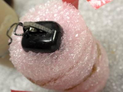
Comparison of bulkheads made of paper with a plywood base (left) or solid balsa (right). Balsa is a bit lighter and simpler, but requires a longer body tube length. (Masking tape is applied for a snug fit.) A paper/wood bulkhead is made from a body tube coupler and two round plywood disks that cap both ends of the coupler. The advantage of a paper/wood bulkhead is that it allows the payload tube to be smaller in length, although overall the payload section will be a bit heavier by a gram or two. If you build this from a 'kit', only use one disk and leave the other end open. The space inside the coupler can be utilized, unlike a solid balsa bulkhead. The next choice (for a paper/wood bulkhead) is whether you want to use a traditional screw eye (you can use the existing one on the model), or go with a lighter Kevlar loop. I made both kinds but I prefer the Kevlar loop because it's slightly lighter and uses up less space.
Two views of a Kevlar loop used instead of a steel screw-eye. Make sure the knot is larger than the hole in the plywood. Next, find, acquire, beg, borrow or steal some padding material. I like to use the expanded plastic foam commonly used for packaging electronic items. This foam is pink in color, which generally denotes it's made so it will not build up a static charge from rubbing. This is not the case with white Styrofoam material. I feel this is safer in the proximity of the altimeter. I don't know that the altimeter is sensitive to damage from static discharges, but I'd rather play it safe. You only need a small amount, so be creative, but look for something light and firm. I imagine foam rubber could work well but I haven't tried it. You could also choose not to make a pre-formed padding and use cotton or wadding, for padding. Avoid fibrous materials like Rockwool; the small fibers may eventually clog the altimeter's sensor port. The next big decision is whether to keep the old screw eye in the nose cone. If it's molded in to the nosecone, the decision is made. If your model has a conventional screw-eye into balsa, you can leave it in and it will be very easy to remove the payload bay and fly it as a "stock" model. If it is holding in additional nose weight - leave it in! Don't remove nose weight or your rocket might go unstable. If you wish to optimize the performance of the rocket you can remove it, but verify the change with RockSim or a string-stability test. Removing the old screw-eye will allow you to make a somewhat shorter payload tube also, so the weight savings and air resistance is theoretically slightly better than leaving the screw eye in. I personally leave mine in.
This “exploded view” with the body tube removed shows the arrangement of parts. Notice the vent holes are below the nose cone’s shoulder and are not covered by the padding. Before you are ready to build, you have one final design chore: Calculate how long to make the payload tube. Add the length of the altimeter (1.93 inches), the thickness of the end padding (count both sides - top and bottom), the shoulder length of the chosen bulkhead (usually 1/2 the total length top-to-bottom), the shoulder length of the nosecone, and the additional length of the screw eye and nose weights if they are still to be attached to the nosecone. This is how long the body tube should be - with the exception of one adjustment: If you are using a solid balsa bulkhead, this dimension should be fine. If you are using a paper/wood bulkhead with one side left open, subtract the inside depth of the bulkhead (usually the length of the bulkhead less about 1/4 of an inch for the wood disk). At this point you can add as many additional inches as you desire for additional payload space or for rocket appearance. Here are two examples: BALSA PAPER/WOOD 1.93 length of Altimeter 1.93 0.375 lower padding thickness 0.375 0.375 upper padding thickness 0.375 0.5 bulkhead shoulder length (1/2 total) 0.5 0.75 nosecone shoulder length 0.75 0.4 remaining screw eye and nose weights 0.4 0 adjustments for paper/wood inside space -0.85 4.33” TOTAL BODYTUBE LENGTH NEEDED 3.48” You can see with the above examples how using a paper/wood bulkhead can conserve body tube length. The difference in weight is not significant between balsa and paper/wood, with balsa saving only about a gram or two. It would be a good idea to calculate and/or weigh the additional weight of the altimeter bay. This might lead to a needed increase of the minimum motor power needed, and can also affect the capacity of the recovery device (i.e. parachute size). I've noticed this especially on small, lighter models, where the added weight of the payload was just too much for a small streamer, and I had to upgrade to a small parachute. Of course, RockSim and other calculator tools here on RocketReviews.com is a great way to do this. Generally the additional weight of the payload bay depends on the diameter, and here are the eight completed weight gains I measured, for both types of bulkheads. This weight includes bulkhead, body tube, paint, glue, all padding and the altimeter one, in grams: BT-20 balsa 12.1 BT-20 paper / wood 12.5 and 13.2 BT-50 balsa 15.0 BT-50 paper / wood 16.5 BT-55 paper / wood 19.2 BT-60 paper / wood 21.5 and 23.6 Remember the motor power may be sufficient, but the additional weight could require a reduction in the delay time. Again, trial and error might work, but RockSim or other calculators are quite capable of doing this before launch day. The last decision to be made - and this is the fun part - is in the design and color of the body tube, and the selection of decals if you want to go that way. You may want to make an effort to match the existing paint scheme of the model, or use a contrasting color or design. I try to find decals that make the model look like it was originally designed that way, and match paint shades as much as possible. In your design, remember that you can either try to hide the vent holes, or accent them. I like to dab a little silver paint around the holes to make them look like a small metal technical device. BuildingFinally, it's time to roll up the sleeves and get to work. Since I had many models I wanted to upgrade, I set up a sort-of production line, cutting and painting many payload bays at the same time. If your bulkhead is balsa, there is nothing to do but to install a screw eye and glue it in place. The hollow bulkhead will need gluing. Glue the lower wood plate into or onto the tube and add glue fillets to both sides. Allow the glue to dry completely and then test fit the bulkhead to the body tubes, adjusting the fit with sandpaper and/or masking tape as needed for a tight fit to the payload tube, and a looser but snug fit to the rocket body tube. Be sure to check the fit of the nosecone to the new payload tube also, as sometimes the fit is different than the nosecone to the rocket body tube. If you decide to use a traditional screw-eye, install it in the base of the bulkhead. Glue it well, or better yet find a small machine-threaded screw eye and nut if possible. You may need to glue a small piece of additional wood to the inside of the bulkhead's wood disk, to give wood-screw threads a firm anchoring. Part of the extra wood disk from the kit can be used. If you choose to use a Kevlar loop instead of a screw eye, make a knot in a 2 or 3-inch thread of Kevlar to form a loop, but leave a bit of tail after the knot to be used to firmly glue this in place. Drill a small hole in the wood base of the bulkhead - make sure the hole is smaller than the knot, otherwise only a bit of glue will have to hold the entire altimeter bay when the model is ejecting and descending! To get the Kevlar through the small hole, slip a small diameter wire (try an old igniter or a single strand of copper from a stranded copper hook-up wire) through the Kevlar loop and bend it in half so it forms a sewing needle of-sorts. You can then use this needle to pull the Kevlar through the hole in the base of the bulkhead before discarding the wire.
Using a thin wire as a “sewing needle” to pull the Kevlar loop through the small hole in the bulkhead’s plywood. Cut out the lower and upper padding disks from your selected padding material. One eighth to one quarter of an inch in vertical thickness should be enough. I use an extra wood disk or the bulkhead as a template. This will make the padding a little larger than necessary, but the flexibility of the padding will allow for a snug fit inside the body tube. At this time I also cut additional disks of padding that will be built-up and used as the padding to surround the Altimeter One. Make enough padding disks to stack up and cover the height of the altimeter, less about one quarter inch. The extra quarter inch space is needed to allow a free space between the altimeter's sensor and the static vent holes. With larger body tubes, you may want to cut additional holes in the padding to make the padding lighter.
Padding cut to fit an Altimeter One in a BT-60 body tube.
Padding length is built-up from a stack of foam disks, with each disk cut to match the shape of the altimeter. After the padding disks are cut, set aside two for the top and bottom padding, and then cut a square hole in the middle of the other disks to be about the size of the altimeter. The square holes don't need to be exact, as the flexibility of the padding will usually work to keep the altimeter snugly in place. When all the disks are cut, stack them up and glue them to each other to produce a cylinder that will hold the altimeter inside. You can also glue the lower padding disk to the bottom of the stack. I used regular wood glue or hot glue, but use whatever works for your chosen padding. Mesure the finished padding, altimeter, screw eye and nose cone shoulder again – just to be sure and then cut the payload body tube to length. Try to make them very precise, as a angled cut will either leave an ugly, drag-producing gap or may cause the rocket to be crooked if fit tight. Next, drill, punch or cut static vent holes to the body tube. Choose 3 or 4 evenly spaced holes around the body’s circumference. I have heard that 3 holes are less likely to allow wind gusts to prematurely trigger an altimeter. The best way to do this is to steal an equivalent-sized paper fin marking guide to evenly mark the holes. The static vent holes should be positioned so that they are about even with the clip hole of the Altimeter One when it is installed in the tube. You could calculate it, but it may be easier to just physically test-fit the bulkhead and altimeter into the tube, and line the vent holes up even with the altimeter's clip mounting hole.
Close up of a static vent hole in a BT-20 tube For small rocket diameters, a 1/8" diameter hole is plenty large. I've used 1/16" holes successfully also. For larger tube diameters or very long payload tubes (if you are adding more empty space), use the larger holes. Make all holes the same diameter - do not get creative and mix hole sizes or hole spacing, as this will only lead to altimeter errors. You may want to coat the insides of the holes with some CA glue, so when it hardens, the extra 'fuzz' or ragged edges can be easily sanded off, leaving you with a nice, clean round hole. This will ensure that the static vent holes will not introduce measurement errors. Before painting the body tube, mark the inside to indicate which side is up. If you assemble the payload with the tube upside-down, the static vent holes might not line up correctly. Since the padding cylinder will fit into the body tube and bulkhead a bit snuggly, I cut a length of ribbon longer than 2X the cylinder length and taped it to the bottom of the padding stack. This allows me to remove the padding from the tube with little effort. The padding glue joints are not very robust; this prevents them from separating at the glue joints when they are pulled out.
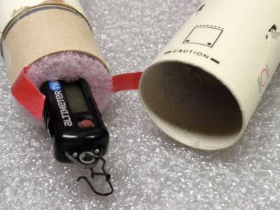
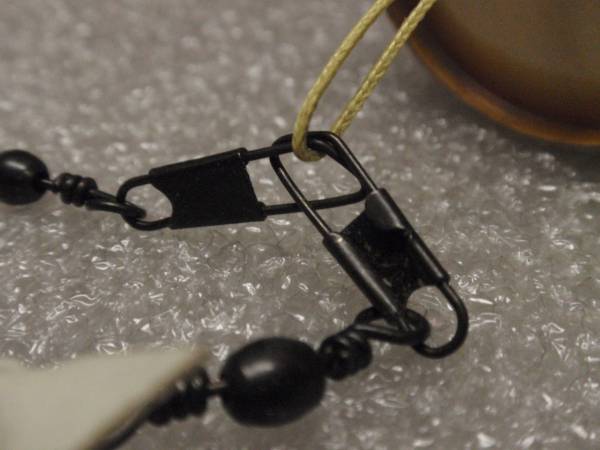
The padding and altimeter can be removed easily if a ribbon is placed under the padding before it is inserted into a hollow bulkhead. If you want to remove the altimeter payload for some flights, you will need to attach both the shock cord and the parachute/streamer to the payload using removable clips. I used fishing swivel clips for this. I can then quickly detach both from the payload and connect them to the nosecone for flying the "stock" rocket. If this isn't necessary, you can just tie both items to the screw eye or Kevlar loop. I have learned that fishing snap hooks sometimes fail. When I connect a shock cord, Kevlar loop and parachute together, I make sure to loop each hook into both other loops. This way the failure of one hook will not separate all three parts, and at least two parts can stay together during the recovery.
The parachute and shock cord clips onto the Kevlar Loop. Notice that the two clips are hooked to each other as well as the payload’s Kevlar loop, so the failure of any one part will still allow the other two to remain attached. When everything is dry, connect all the pieces and you are ready to fly! Just make sure that the nosecone and bulkhead are pretty tight, you don't want the altimeter to get lost on a rough ejection. Also make sure that the payload separates easily from the rocket, just as you would a normal nosecone.
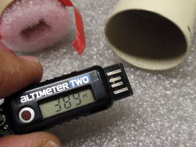
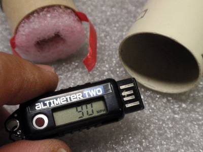
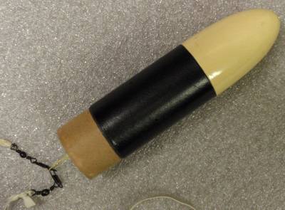
Completed Altimeter Payload on a Big Bertha. Vent holes are hard to see with the black paint. Launch Day Before launch, remember to clear the Altimeter One before inserting it into the payload bay. As long as it has a good charge, it will be ready for the launch even if it is delayed. It's better to pack a plastic parachute or streamer last so it has less time to 'set' in place while you prepare the Altimeter One. For the Altimeter Two (which senses movement at launch), clear and pack the altimeter last, and handle the rocket carefully after that. I have found the hard way that it will trigger from even minor bumps and shaking. As soon as one of my models land I immediately want to know how high it went. Rather than wait to return to the range box and use tools to extract it, tie a small string or ribbon to the Altimeter One. Then, just remove the nose cone and yank out the Altimeter One right away. That way I can walk back while telling everybody how high it went - whether they want to know or not! |
|||
|
|


Rich DeAngelis (August 6, 2012)